Concrete filled steel tube transfer joint structure and construction method thereof

A technology of steel pipe concrete and transfer nodes, which is applied in the direction of building structure and construction, and can solve the problems of reduced space for transfer floors, low bearing capacity of reinforced concrete components, and difficulties in pouring and tamping concrete for welding construction, so as to solve the welding workload Larger, less on-site welding workload, and guaranteed construction quality

Active Publication Date: 2016-01-13
SOUTH CHINA UNIV OF TECH
View PDF5 Cites 5 Cited by
  • Summary
  • Abstract
  • Description
  • Claims
  • Application Information

AI Technical Summary

Problems solved by technology

The bearing capacity of reinforced concrete members is low. In order to meet the safety requirements, the cross-sectional size of the inclined column and the volume of the joints are large, which will reduce the use of space in the transfer floor building and inconvenience the passage of pipelines.
[0007] (2) Node construction is difficult
However, the upper and lower inner partitions are installed in the core area of ​​the joint, and the welding workload is relatively large. When the cross-sectional size of the pillar is small, the welding construction and concrete pouring are difficult, and the construction quality is difficult to guarantee

Method used


Image

  • Concrete filled steel tube transfer joint structure and construction method thereof
  • Concrete filled steel tube transfer joint structure and construction method thereof
  • Concrete filled steel tube transfer joint structure and construction method thereof

Examples


Embodiment 1

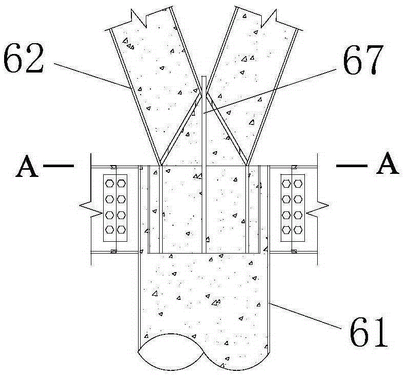
[0071] A steel pipe concrete conversion node structure, including a pillar 61, a slanting column and a receiving frame 63, the slanting column is fixedly connected to the receiving frame, and the receiving frame is fixedly arranged inside the pillar and located at the top of the pillar.

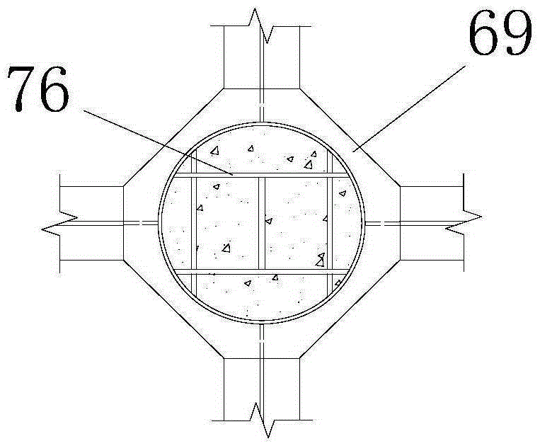
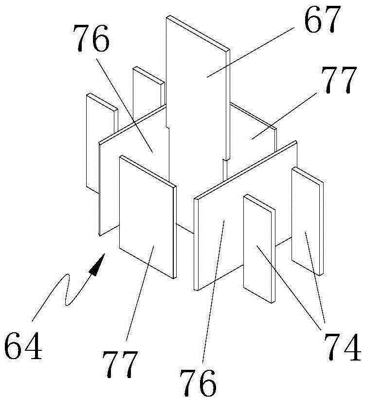
[0072] Preferably, the receiving frame includes a vertical inner rib 64, and there is a cross section on the inclined column, and the cross section includes a cross section 65. The shape formed by the vertical inner rib corresponds to the shape of the cross section and a connecting rib extends out. The connecting ribs are fixedly connected to the inner walls of the pillars, and the inclined columns are fixed to the vertical inner ribs through the section. Preferably, the top surface of the vertical inner rib is flush with the top surface of the pillar.

[0073] Preferably, the receiving frame is also provided with a protruding vertical inner rib plate 67 whose upper part protrudes from the pi...

Embodiment 2

[0085] The difference between this embodiment and the first embodiment is that the slanted columns are two circular slanted columns 84, the cross section of the slanted columns is an arc-shaped cross section, and the cross section of the two slanted columns forms an arc section , the vertical section of the inclined column is an arc-shaped vertical section, the vertical inner ribs enclose an arc joint 85, the protruding vertical inner ribs are arranged in the middle of the arc joint, and the arc cross-sections are fixedly connected To the arc joint, the arc-shaped vertical sections of the two inclined columns are fixedly connected to the two sides of the protruding vertical inner ribs; the connecting ribs are fixedly connected to the outer sides of the vertical inner ribs surrounding the arc joint, The protruding end of the connecting rib is fixedly connected to the inner wall of the pillar.

[0086] The vertical inner ribs can be two arc-shaped vertical inner ribs 86, and the...

Embodiment 3

[0088] A construction method for a steel pipe concrete conversion node structure, which cuts the nozzle of the inclined column to be connected, and cuts out the cross section and the vertical section respectively;

[0089] The vertical inner ribs are made to have the same shape as the cross-section of the slanted column and the connecting ribs protrude, and then the protruding vertical inner ribs are placed in the middle of the shape surrounded by the vertical inner ribs, and the protruding connecting ribs The plate is welded to the inner wall of the pillar, and the upper part of the protruding vertical inner rib protrudes outside the pillar;

[0090] Butt the pillar with the lower CFST column, and pour concrete into the node area;

[0091] Hoist the inclined column in place and weld the cross section and vertical section to the vertical inner floor and the protruding vertical inner floor respectively;

[0092] After the concrete in the joint area and the pillar is solidified...


PUM


Abstract

The invention discloses a concrete filled steel tube transfer joint structure and a construction method thereof. The concrete filled steel tube transfer joint structure comprises a strut, a batter post and a socket frame; the batter post is fixedly connected to the socket frame; the socket frame is fixedly arranged inside the strut and located at a top end of the strut; the socket frame comprises a vertical inner ribbed plate; the batter post is provided with a section including a cross section; a shape of the vertical rib ribbed plate corresponds to a shape of the cross section and a connecting ribbed plate extends out of the vertical inner ribbed plate; the connecting ribbed plate extending out is fixedly connected to an inner wall of the strut; the batter post is fixed on the vertical inner ribbed plate through the section. The concrete filled steel tube transfer joint structure is integrated with the advantages of a concrete-filled steel tube and a battery post transfer structure, and has the advantages of direct force transfer, high bearing capacity, small sectional dimension of the component, good utilization of building space, no need for support formwork, small field welding workload, guaranteed construction quality and the like. Two batter posts and a beam system form a triangular force transfer mode, and meanwhile, excellent side force resisting capability is realized.

Description

technical field [0001] The invention relates to a building transfer node structure and a construction method thereof, in particular to a steel pipe concrete transfer node structure and a construction method thereof. Background technique [0002] As the functions and forms of high-rise and super high-rise buildings continue to diversify, the application of transfer floors is becoming more and more extensive. The inclined column transfer structure has transfer members, which mainly bear the axial load, has the characteristics of short force transmission path and small cross-sectional size of the transfer members, which is beneficial to the use of architectural space, so it has a wide application prospect. In addition, because the transition member mainly bears axial load, it is suitable to adopt the CFST member. The size of steel pipe concrete members is smaller than that of traditional reinforced concrete members, and it saves formwork and does not need to bind steel bars. T...

Claims


Application Information

Patent Timeline
Patent Type & Authority Applications(China)
IPC IPC(8): E04B1/58E04B1/30
Inventor 左志亮蔡健杨春陈庆军姜正荣刘达鑫张成天
Owner SOUTH CHINA UNIV OF TECH
Why Eureka
Try Eureka