Virtual operating room integration

a virtual operating room and operating room technology, applied in the field of virtual operating room integration, can solve the problems of inability to place the front panel controls of the surgical equipment within the sterile field, the necessity to rely on an assistant for indirect control of non-sterile surgical equipment the need to rely on an assistant for indirect control can become a distraction, so as to eliminate clutter and the risk of falling, direct and accurate control of the surgical instrumen

Inactive Publication Date: 2008-01-08
CONMED CORP
View PDF28 Cites 751 Cited by
  • Summary
  • Abstract
  • Description
  • Claims
  • Application Information

AI Technical Summary

Benefits of technology

[0013]The present invention involves a system and method for controlling and using equipment in an operating room through the use of virtual control devices. The virtual control devices project images on surfaces, and the surgeon interacts with the images to control the equipment, such as surgical equipment and patient monitoring equipment. The images created by the virtual control devices may include a front control panel to control the equipment and a foot switch to activate and deactivate the surgical equipment. The images from the virtual control devices may be displayed and presented at locations which are within the sterile field so that the surgeon may interact with them directly rather than rely on surgical personnel to achieve control and adjustment of the equipment. More direct and accurate control over the surgical instrument is obtained. Traditional foot switches with cables are eliminated, thereby eliminating the clutter and risk of tripping created by such equipment as well as a source of pathogens within the operating room. The virtual control devices can be positioned for the most expeditious use, and the images from the virtual control devices can be moved from one location to another by changing the location of the light projection which creates the images.
[0014]The present invention also involves a system and method for displaying information obtained from patient monitoring equipment and the surgical equipment in an expeditious, convenient and non-distracting manner for use by the surgeon during the surgical procedure. Display images are projected in a manner which does not require the surgeon to substantially divert his attention from the surgical site, such as by presenting the information in a heads up display projected onto a face shield worn by the surgeon. In addition or alternatively, the display images are projected in a manner which minimizes the amount of diversion of attention required from the surgeon, and in a manner which makes the display images conveniently observable to the operating room personnel. The information displayed may include the control, status and functionality information of the surgical equipment and vital statistics and signs indicating the condition of the patient. The images presenting the information may be displayed and presented at locations within the sterile field so that the surgeon may observe the information directly while performing the procedure rather than rely on surgical personnel to communicate that information. More immediate and accurate communication of information is obtained. The information displays can be positioned for the most expeditious use, and the images can be moved from one location to another by changing the location of the light projection which creates the images.
[0016]The communication links to establish this functionality are preferably wireless, to eliminate the clutter and risks of tripping over further physical objects within the operating room and to facilitate advantageous positioning of the virtual control devices. The functionality of the present invention is available to be used with a variety of different types of surgical equipment made by different manufacturers, even though that surgical equipment was not originally intended to be used in the manner contemplated by the present invention.

Problems solved by technology

The front panel controls of the surgical equipment cannot be positioned within the sterile field where the surgeon is operating because it is not possible to disinfect and sterilize the entire surgical equipment of which the front panel controls are a part.
Adjustments to the front panel controls are achieved in response to verbal commands from the surgeon, and such verbal communication may be prone to misinterpretation.
In any event, the necessity to rely on an assistant for indirect control over non-sterile surgical equipment can become a distraction to the surgeon, particularly in procedures which require numerous adjustments during the course of the procedure.
Failing to establish or remember the preferred settings can require additional adjustments to be made during the procedure and is distracting to the progress of the procedure.
However, foot switches are relatively bulky and heavy and are connected to the surgical equipment by a cable that extends along the floor.
Foot switches and their cables can clutter the floor of an operating room, particularly when more than one foot switch is used.
The foot switches and their cables may pose a tripping hazard that can be especially distracting to the numerous people working and moving about the operating table.
Even though they are located outside of the sterile field, foot switches and their cables are a potential source of introducing pathogens into the operating room.
Moving the foot switch back and forth in this manner is difficult due to its bulk and because the cable extending from the foot switch further complicates movement.
Moving the foot switch is time consuming, inconvenient and inefficient because of the delay involved in moving and positioning the foot switch.
When the foot switch is moved, or when the surgeon shifts his or her position, the surgeon may experience difficulty in locating the position of the foot switch for use, thereby distracting attention from the procedure.
Allowing the surgeon to interact with a holographic image allows the surgeon to establish direct control over the surgical equipment without compromising the sterile field, but holographic images introduce new problems.
One such problem stems from the fact that holographic images can only be viewed from a relatively narrow field of vision, which means that they cannot always be seen by the surgeon.
Moreover, because the hologram exists in three-dimensional space, an individual or object can inadvertently move through the three-dimensional space and interact with the hologram in such a way to create an unintended adjustment of or control over the surgical equipment.
The holographic controls for surgical equipment do not effectively deal with the problem of clutter caused by the bulky foot switches and their attached cables beneath the operating table.
Holographic controls can not be conveniently located near the floor because of the necessity to focus the holographic image at a location where interaction with it is possible.
Another circumstance which may result in distraction or inconvenience to the surgeon during the procedure relates to informing the surgeon of various physiological and other conditions of the patient during the procedure.
These monitors and displays are large and complex devices and are sometimes integrated with the patient monitoring equipment itself, thereby making it essentially impossible to sterilize this equipment.
Periodically diverting the surgeon's attention away from the surgical site is a distraction and a complication to the surgeon, particularly in very intense and tedious procedures.
Relying on an assistant to communicate relevant patient information to the surgeon is subject to miscommunication and misinterpretation.
The need to continually divert attention from the surgical site is an inconvenience and distraction.
However, since the surgeon cannot divert his or her attention from the surgical site, it becomes impossible to simultaneously monitor the performance of the surgical equipment while using that surgical equipment.

Method used


Image

  • Virtual operating room integration
  • Virtual operating room integration
  • Virtual operating room integration

Examples


Embodiment Construction

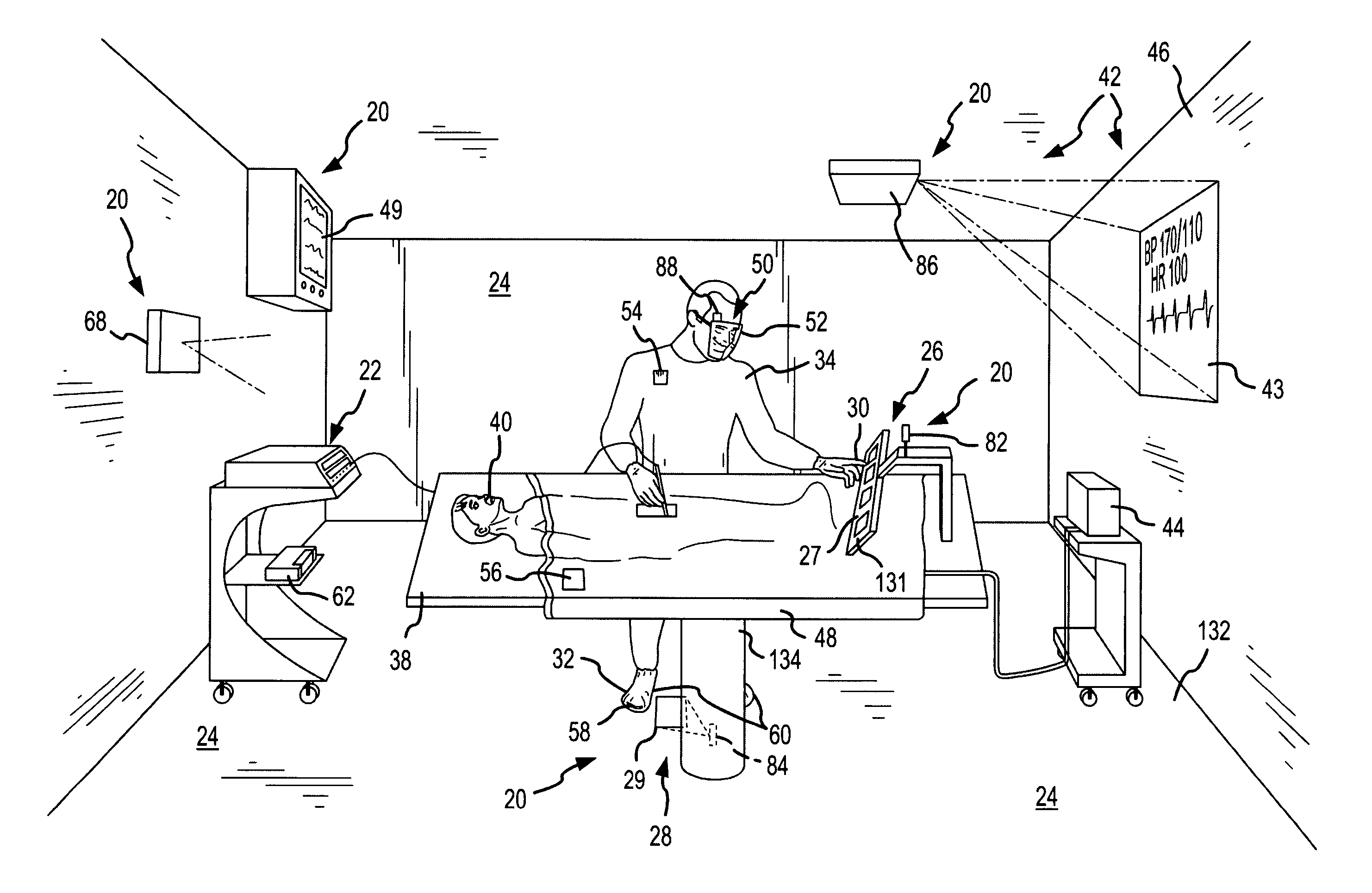
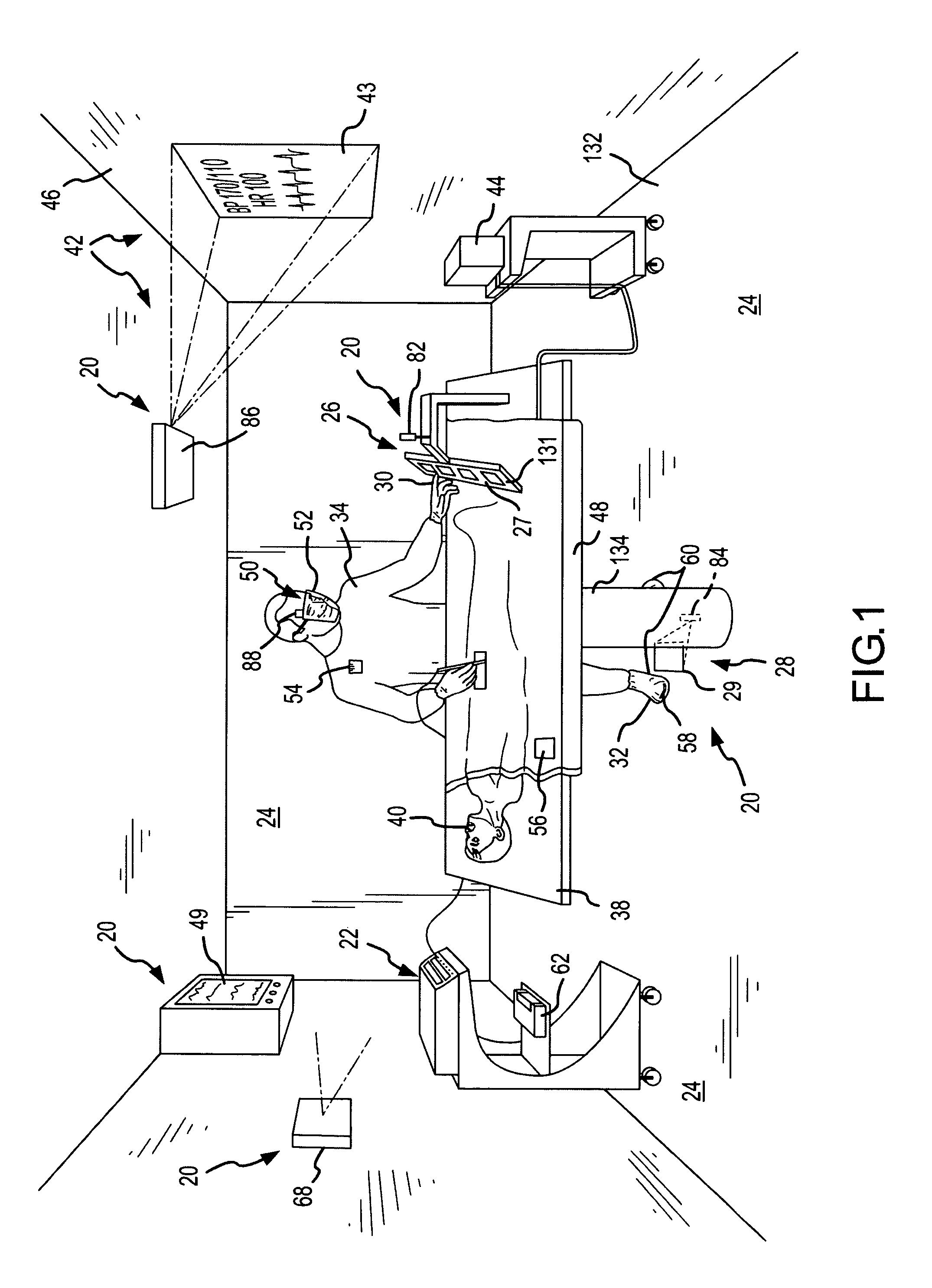
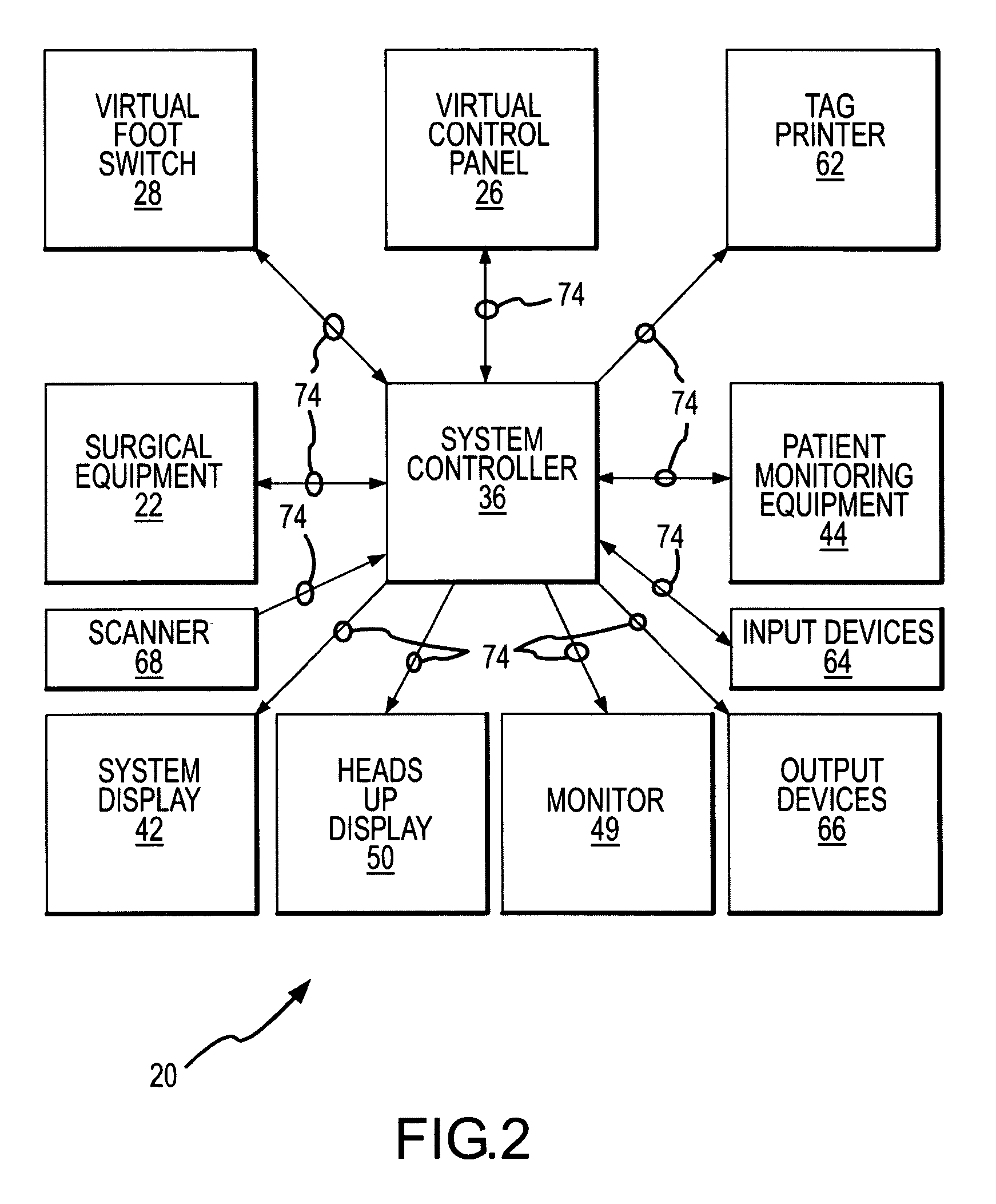
[0031]An exemplary form of the present invention is embodied in a virtual integration or control system 20 for controlling surgical equipment 22, among other things, in an operating room 24, as shown in FIGS. 1-3. The virtual control system includes a virtual control panel 26 and a virtual foot switch 28 created by projecting an image 27 of a control panel and an image 29 of a foot switch. Physical interaction of a finger 30 or foot 32 of the surgeon 34 with the control panel image 27 and the foot switch image 29, respectively, is then interrogated and interpreted as a control input to the surgical equipment. A system controller 36 (FIGS. 2 and 3) of the virtual control system 20 controls the surgical equipment 22 in response to that interrogation and interaction. For example, direct physical interaction of the surgeon's finger 30 with the projected control panel image 27 may result in adjusting the output power and output signal characteristics from the surgical equipment 22, and d...


PUM


Abstract

A virtual control system for an operating room establishes virtual control devices to control surgical equipment and patient monitoring equipment and to display control, status and functionality information concerning the surgical equipment and condition information of the patient. The virtual control devices permit direct interaction by the surgeon while maintaining a sterile field, and avoid the use of actual physical devices and electrical cables connecting them to the surgical equipment.

Description

CROSS-REFERENCE TO RELATED APPLICATION[0001]This invention is related to another invention made by the present inventor for Virtual Control of Electrosurgical Generator Functions described in U.S. patent application Ser. No. (24.355), filed concurrently herewith. The subject matter of this concurrently filed application is incorporated herein by this reference.FIELD OF THE INVENTION[0002]This invention relates to integrating surgical equipment in one or more operating rooms using virtual control devices and optical displays. More particularly, the present invention relates to a new and improved virtual control system and method which optically senses the position of a surgeon's foot or finger with respect to a projected image of a virtual control device associated with the surgical equipment and which controls the surgical equipment in relation to the sensed position of the foot or finger. The present invention also relates to a new and improved system and method for displaying info...

Claims


Application Information

Patent Timeline
Patent Type & Authority Patents(United States)
IPC IPC(8): A61B1/00A61B18/04A61B18/18A61N1/00G05B15/00A61B17/00A61B18/12
CPCA61B18/1206A61B2017/00199G16H20/40G16H40/63
Inventor MCGREEVY, FRANCIS T.
Owner CONMED CORP
Why Eureka
Try Eureka