Tool kit

a tool kit and tool technology, applied in the direction of machine supports, containers preventing decay, sealing, etc., can solve the problem that the hanging block is not easy to be unexpectedly opened, and achieve the effect of convenient closing/opening and sufficient fixing for

Inactive Publication Date: 2008-01-15
LEE CHANG CHUAN
View PDF18 Cites 4 Cited by
  • Summary
  • Abstract
  • Description
  • Claims
  • Application Information

AI Technical Summary

Benefits of technology

[0004]It is therefore a primary object of the present invention to provide a tool kit structure in which one side of the upper box cover is formed with a recessed section. Two lateral sides of the recessed section are respectively formed with two longitudinally extending lugs opposite to each other. A hanging block is connected with a bottom of the recessed section. The hanging block is conveniently closable / openable. After the hanging block is closed into the recessed section, the lugs serve to abut against the hanging block to provide sufficient fixing force. Therefore, the hanging block is not easy to be unexpectedly opened due to mis-touch.
[0005]It is a further object of the present invention to provide the above tool kit structure in which the top of the upper box cover is formed with a turning depression near one side of the upper cover. After the hanging block is closed into the recessed section, the turning depression serves as a turning space for a user to easily open / close the hanging block.
[0006]According to the above objects, the tool kit structure of the present invention includes a tool kit having a bottom box and an upper box cover. One side of the upper cover is formed with a recessed section. Two lateral sides of the recessed section are respectively formed with two longitudinally extending lugs opposite to each other. A hanging block is connected with a bottom of the recessed section. The hanging block is conveniently closable / openable. The hanging block is formed with a hanging hole for hanging the tool kit for exhibition. The top of the upper box cover is formed with a turning depression near the side of the upper cover. After the hanging block is closed into the recessed section, the turning depression serves as a turning space for a user to easily turn the hanging block.

Problems solved by technology

Therefore, the hanging block is not easy to be unexpectedly opened due to mis-touch.

Method used


Image

  • Tool kit
  • Tool kit
  • Tool kit

Examples


Embodiment Construction

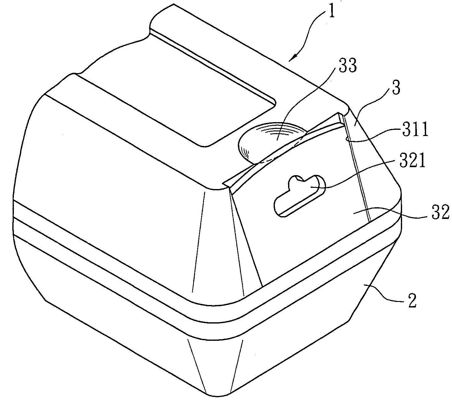
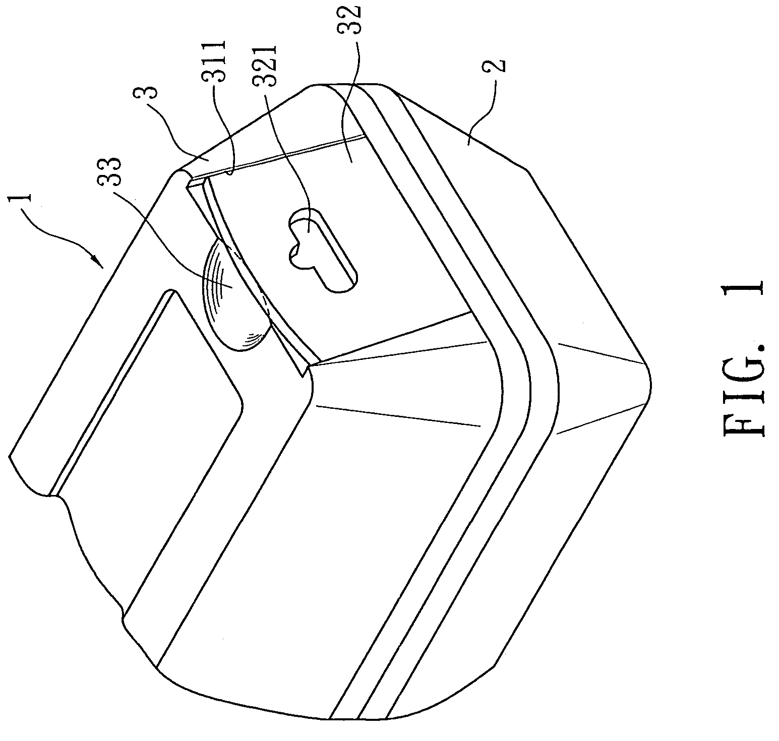
[0015]Please refer to FIG. 1. The tool kit structure of the present invention includes a tool kit 1 having a bottom box 2 and an upper box cover 3. One side of the upper box cover 3 is formed with a recessed section 31. Two lateral sides of the recessed section 31 are respectively formed with two longitudinally extending lugs 311 opposite to each other. A hanging block 32 is connected with a bottom of the recessed section 31. In this embodiment, top end of the hanging block 32 is arced for convenient opening / closing. The hanging block 32 is formed with a hanging hole 321 for hanging the tool kit 1 to exhibit the same. The top of the upper box cover 3 is formed with a turning depression 33 near the side of the upper box cover 3. Accordingly, after the hanging block 32 is closed into the recessed section 31, the turning depression 33 enables a user to easily turn the hanging block 32.

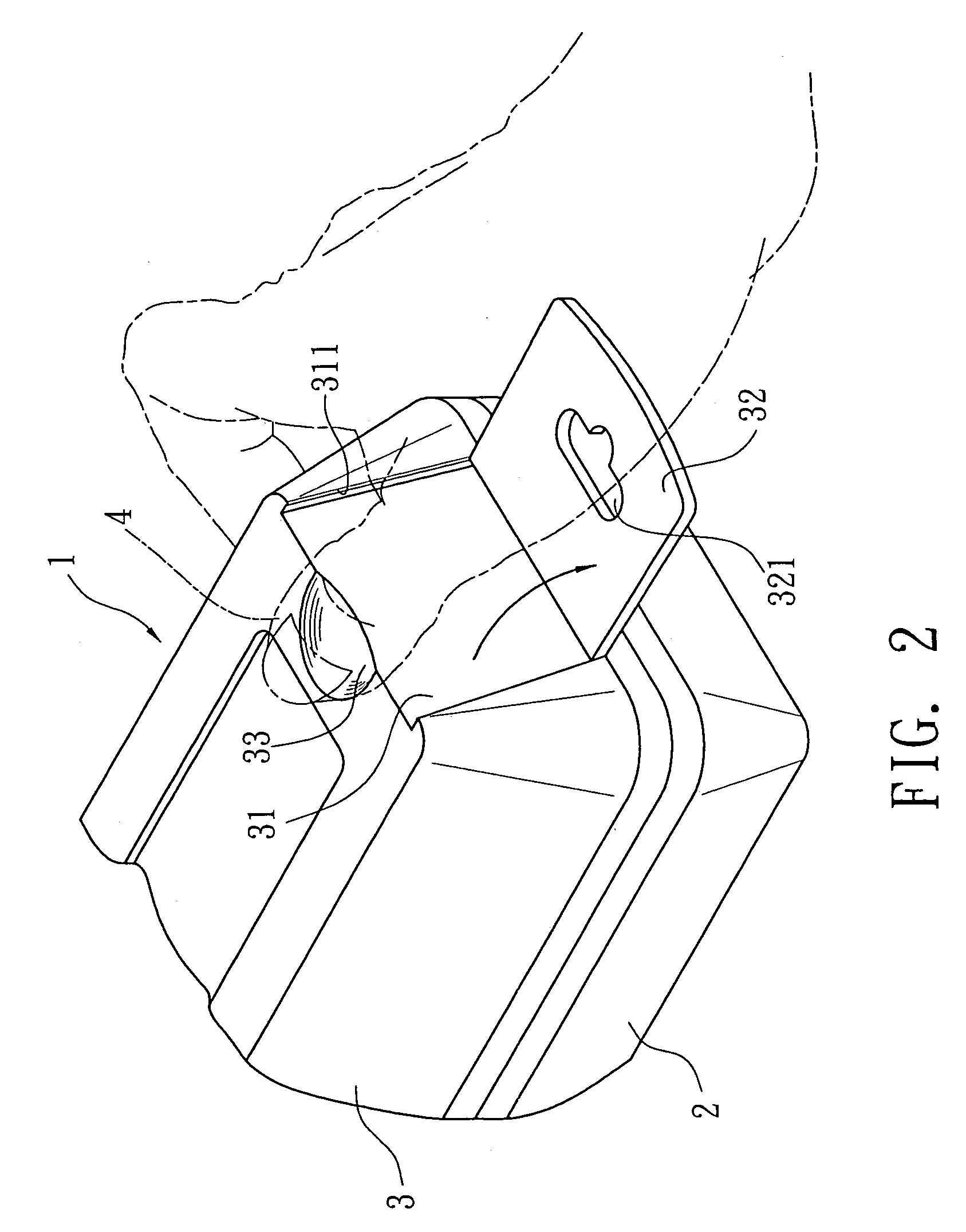
[0016]Referring to FIG. 2, after the hand tools are placed in the tool kit, in the case that the stora...


PUM


Abstract

A tool kit structure including a tool kit having a bottom box and an upper cover. One side of the upper cover is formed with a recessed section. Two lateral sides of the recessed section are respectively formed with two longitudinally extending lugs opposite to each other. A hanging block is connected with a bottom of the recessed section. The hanging block is conveniently closable / openable. The hanging block is formed with a hanging hole for hanging the tool kit for exhibition. The top of the upper cover is formed with a turning depression near the side of the upper cover. After the hanging block is closed into the recessed section, the turning depression serves as a turning space for a user to easily turn the hanging block. By means of the hanging block, the tool kit can be horizontally placed or vertically hung.

Description

BACKGROUND OF THE INVENTION[0001]The present invention is related to an improved tool kit structure, and more particularly to a tool kit structure which can be horizontally placed or vertically hung.[0002]The existent tool kit is generally horizontally placed. When used, a user can open an upper cover of the tool kit and take out a hand tool from the tool kit. After used, the hand tool is folded and horizontally placed into the bottom of the tool kit. Such horizontally placed tool kit necessitates greater room for storage. In addition, a user often can hardly conveniently take out and place in the hand tool.[0003]FIG. 7 shows an improved tool kit for overcoming the above problem. One side of the bottom box 61 of the tool kit 6 is formed with two recessed sections 62 in which two hanging blocks 63 are rotationally foldably connected. Each hanging block 63 is formed with a hanging hole 631. By means of the hanging hole 631, after the hanging block 63 is unfolded, the tool kit 6 can be...

Claims


Application Information

Patent Timeline
Patent Type & Authority Patents(United States)
IPC IPC(8): F16M11/00
CPCB25H3/003Y10S206/806
Inventor LEE, CHANG CHUAN
Owner LEE CHANG CHUAN
Why Eureka
Try Eureka