
Variable ride control

a variable-speed control and suspension technology, applied in vehicle springs, resilient suspensions, transportation and packaging, etc., can solve the problems of difficult to automatically accommodate all these applications and configurations, and skid steer vehicles with suspensions are prone to oscillation

Active Publication Date: 2008-01-15
BLUE LEAF I P INC
View PDF9 Cites 25 Cited by
  • Summary
  • Abstract
  • Description
  • Claims
  • Application Information

AI Technical Summary

Problems solved by technology

Skid steer vehicles with suspensions are prone to oscillating when driven over rough terrain with changing loads.
It is difficult to accommodate all these applications and configurations automatically.

Method used


Image

  • Variable ride control
  • Variable ride control
  • Variable ride control

Examples


Embodiment Construction

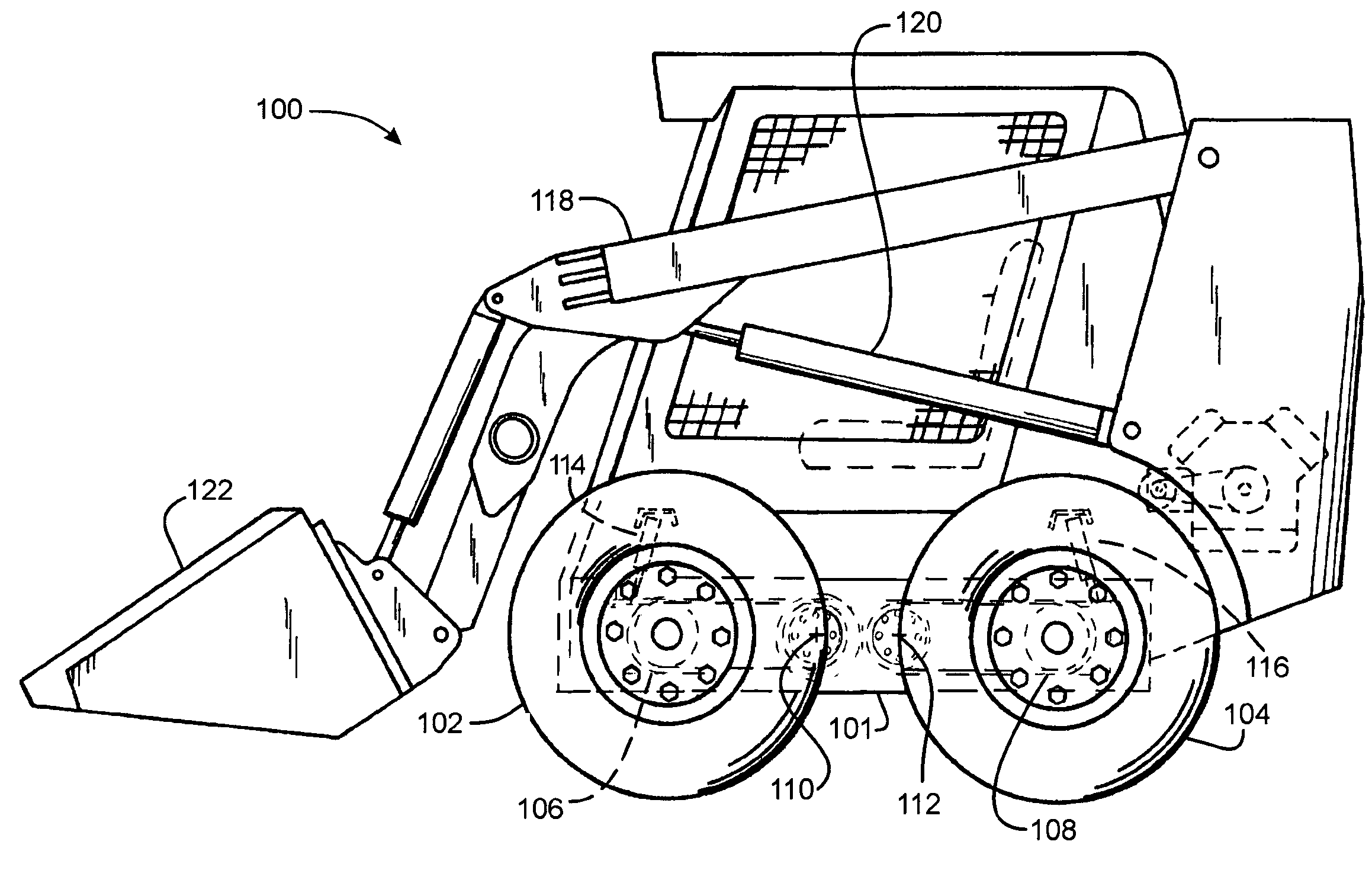
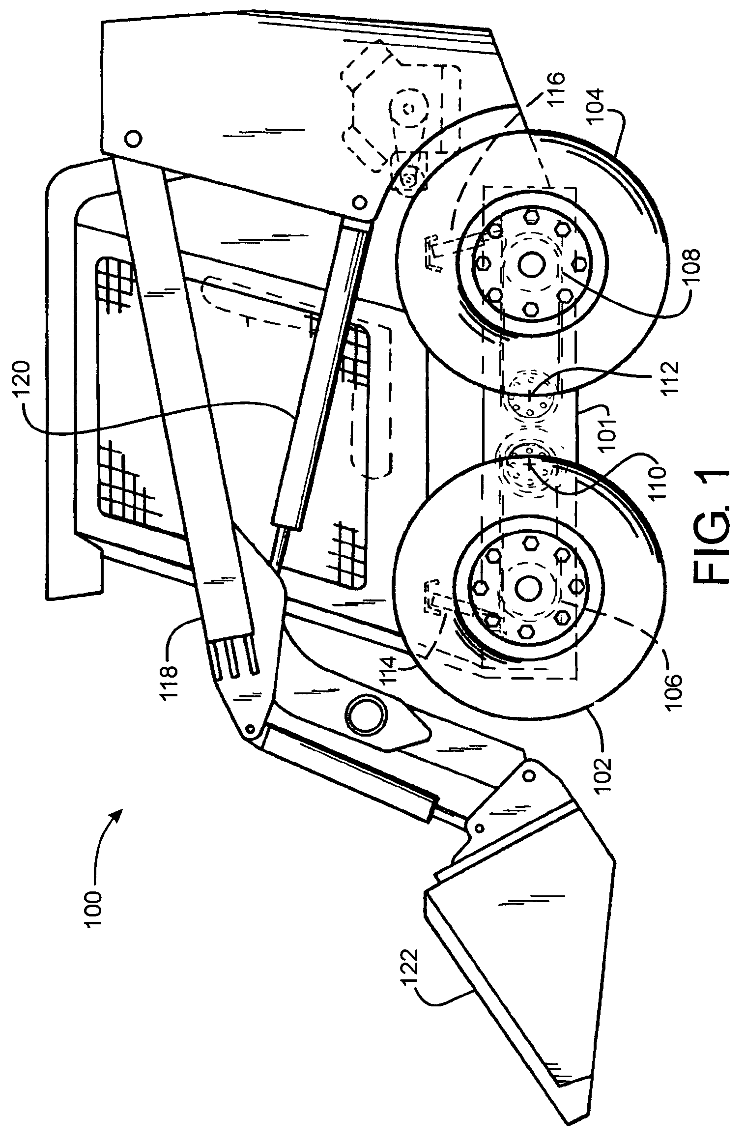
[0018]FIG. 1 shows the left side of a skid steer vehicle 100 having a chassis 101. The left side of vehicle 100 has two wheels 102, 104, that are coupled to a forwardly extending suspension control arm 106 and a rearwardly extending suspension control arm 108, respectively. The control arms are pivotally coupled to the chassis to pivot with respect thereto about parallel and laterally extending pivotal axes 110, 112. The left side of the vehicle also includes two hydraulic damping cylinders 114, 116, a loader lift arm 118, a loader lift arm cylinder 120, and a bucket 122. The loader lift arm cylinder 120 is coupled to and between loader lift arm 118 and chassis 101, to lift arm 118 and hence bucket 122 with respect to chassis 101. A second loader lift arm and loader lift arm cylinder may be provided on the other side of the vehicle in mirror relation to the arm and cylinder shown in FIG. 1.

[0019]Damping cylinder 114 is coupled to and between the free end of front control arm 106 and...


PUM


Abstract

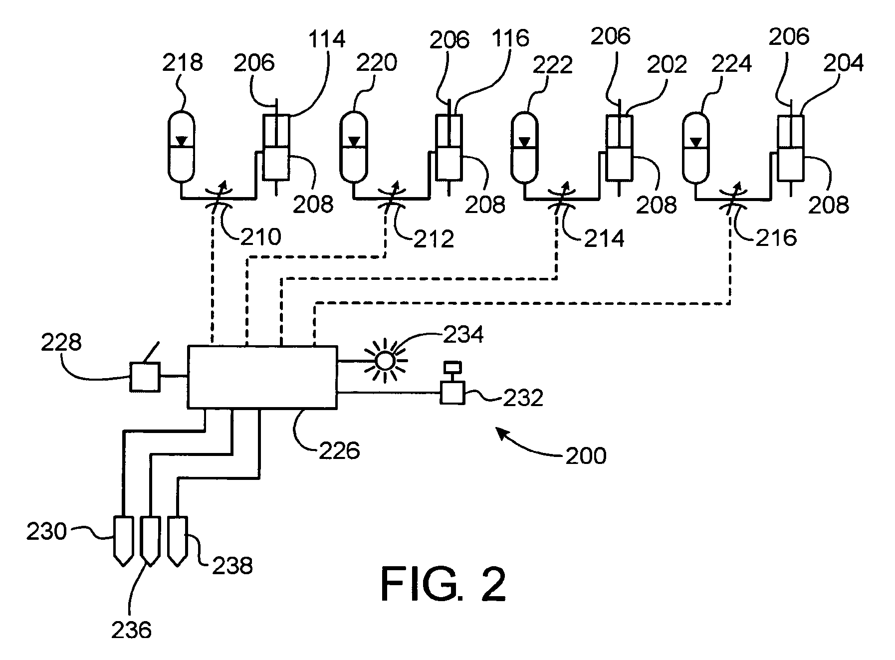
A skid steer vehicle has a chassis with four drive wheels suspended from the chassis that are damped by four damping cylinders. An electronic controller varies the damping of the cylinders in an automatic mode, based on certain operational parameters of the vehicle, and in a manual mode in response to operator selection of a desired degree of suspension damping.

Description

FIELD OF THE INVENTION[0001]The invention relates generally to skid steer vehicles. More particularly, it relates to skid steer vehicles having damped suspensions. Even more particularly, it relates to systems for damping the oscillations of the suspensions.BACKGROUND OF THE INVENTION[0002]Skid steer vehicles have recently come on the market with suspensions that permit the chassis to move up and down with respect to the ground. Prior skid steer vehicles were rigidly supported for movement over the ground.[0003]Skid steer vehicles with suspensions are prone to oscillating when driven over rough terrain with changing loads. They have a relatively small wheel base, and as a result, when they are driven over the ground the oscillations of the suspensions can be substantial, depending, among other things, on the vehicle load, the vehicle speed and the terrain over which the vehicle is operating.[0004]What is needed, therefore, is a skid steer vehicle having a system and method for autom...

Claims


Application Information

Patent Timeline
Patent Type & Authority Patents(United States)
IPC IPC(8): B60G17/00B60G17/019B60G9/04
CPCB60G17/0152B60G2202/154B60G2300/022B60G2400/204B60G2400/252B60G2400/60B60G2500/10
Inventor LAMELA, ANTHONY J.BATEMAN, TROY D.FELSING, BRIAN E.DIX, PETER J.SHORE, DANIEL B.LIN, HONG-CHIN
Owner BLUE LEAF I P INC
Learn More