High power LED color bulb with infrared remote function

a color bulb and infrared technology, applied in the field of led lamps, can solve the problems that the infrared remote function cannot be integrated into the conventional lamp, and cannot allow the use of a traditional controller, so as to avoid overheating from hea

Inactive Publication Date: 2008-01-15
ANTEYA TECH CORP +1
View PDF15 Cites 82 Cited by
  • Summary
  • Abstract
  • Description
  • Claims
  • Application Information

AI Technical Summary

Benefits of technology

[0010]The high power LED color bulb has a reflector having a front and a rear opening and a light guide hole, a light guide bar received inside light guide hole, an LED module with LED chips and a bulb cover with a controlling circuit board. The LED module is mounted on a rear end of the reflector with the LED chips inside the reflector. The controlling circuit board is inside the bulb cover, is connected electronically to the LED module and has an infrared sensor aligned with the light guide bar of the reflector. When an infrared signal comes through the front opening of the reflector, the infrared signal passes through the light guide bar and is received by the infrared sensor. Since the infrared sensor is behind the reflector and the LED chips, the infrared sensor avoids overheating from heat produced by the LED chips and does not have to be replaced simultaneously with the color bulb.

Problems solved by technology

1. Because a traditional lamp only has a single color bulb, it only requires a switch to turn the color bulb on and turn off. However, using a high power LED color bulb instead of a traditional single color bulb in the lamps does not allow a traditional controller to be used, since the high power LED color bulb has several different color modes (e.g. 16 colors). Therefore, a remote controller is required when the lamp uses a high power LED color bulb.
2. If a conventional single color bulb is to be changed to a color bulb, the lamp with the color bulb still does not have an infrared remote function unless an infrared receiver is mounted inside the lamp. Therefore, an infrared remote function cannot be incorporated into a conventional lamp by installing a high power LED color bulb.

Method used


Image

  • High power LED color bulb with infrared remote function
  • High power LED color bulb with infrared remote function
  • High power LED color bulb with infrared remote function

Examples


Embodiment Construction

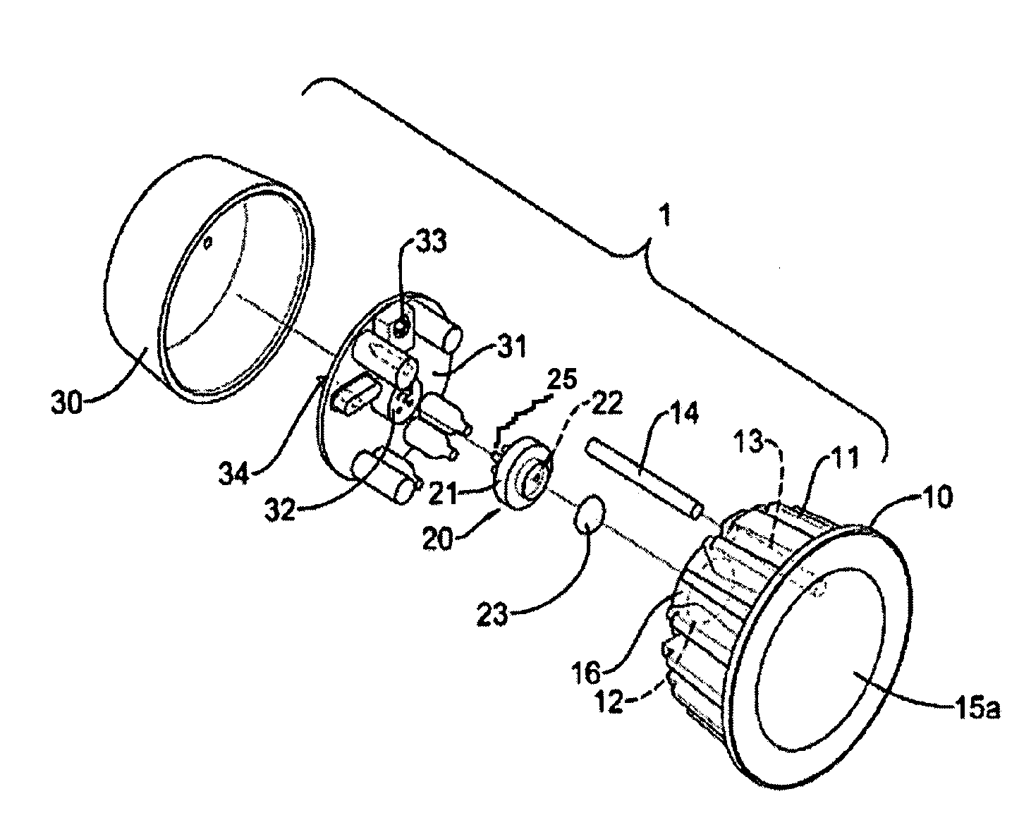
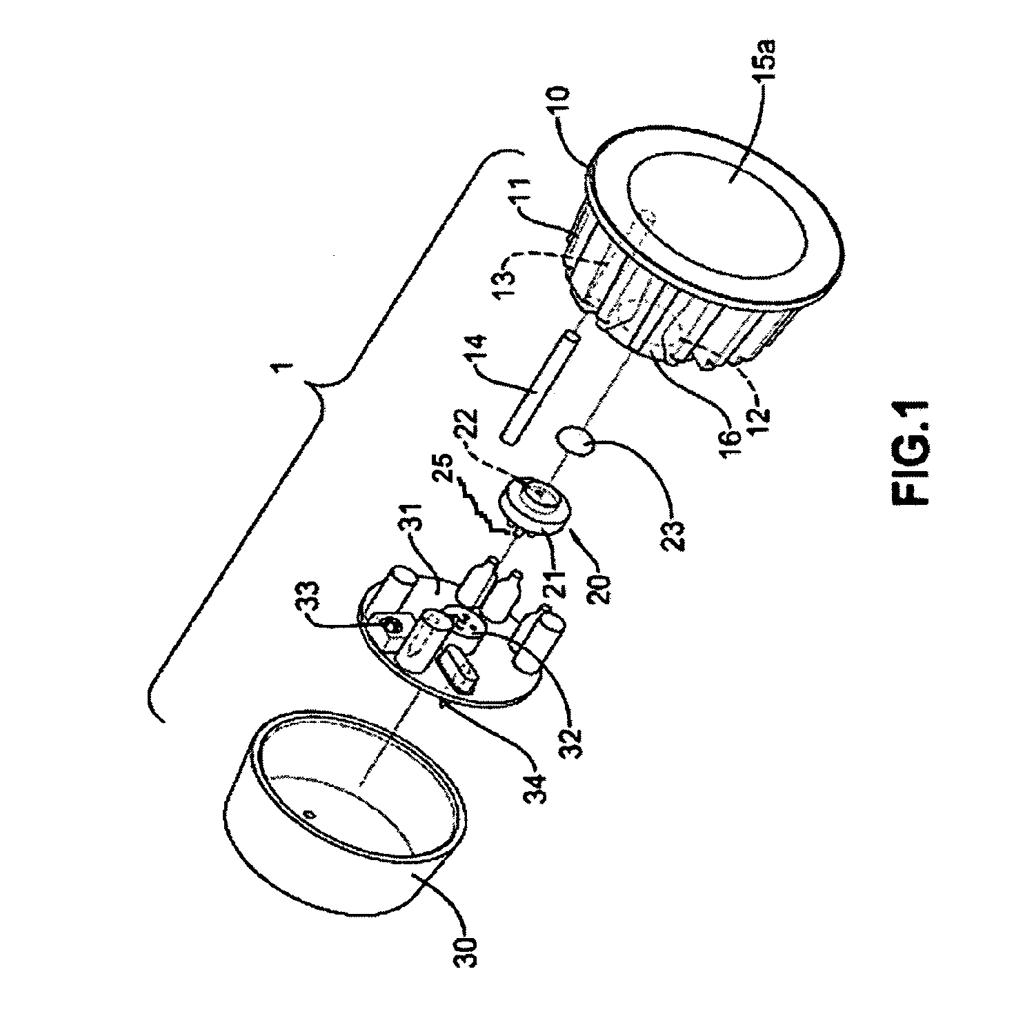
[0019]With reference to FIG. 1, a first embodiment of a high power LED color bulb (1) has a reflector (10), an LED module (20) and a bulb cover (30).

[0020]The reflector (10) has a body, multiple radiator fins (11), a reflecting inside, a reflector joint (16), a light guide hole (13), an optional light guide bar (14) and an optional penetrating light sheet (15a). The body could be formed in a horn or a bowl shape and made of metal, plastic or other materials with high thermal conductivity and has a front, a rear and a front opening. The multiple radiator fins (11) are formed outside the body to radiate heat from the reflector (10). The reflector joint (16) is formed on the rear of the body and has a central penetrating hole (12). The light guide hole (13) is defined through the body from the front to the rear. The light guide bar (14) is held inside the light guide hole (13). The penetrating light sheet (15a) covers the front opening of the body to allow light go through. With furthe...


PUM


Abstract

A high power LED color bulb with infrared remote function has a reflector having front and rear openings and a light guide hole, a light guide bar received inside light guide hole, an LED module with LED chips and a bulb cover with a controlling circuit board. The LED module is mounted on a rear end of the reflector with the LED chips inside the reflector. The controlling circuit board is inside the bulb cover, is connected electronically to the LED module and has an infrared sensor aligned with the light guide bar of the reflector. When an infrared signal comes through the front opening of the reflector, the infrared signal passes through the light guide bar and is received by the infrared sensor. Since the infrared sensor is behind the reflector and the LED chips, the infrared sensor avoids overheating from heat produced by the LED chips and does not have to be replaced simultaneously with the color bulb.

Description

BACKGROUND OF THE INVENTION[0001]1. Field of the Invention[0002]This invention relates to an LED lamp, and especially for a high power LED color bulb with an infrared remote function.[0003]2. Description of the Related Art[0004]The function of LEDs has changed from the earliest stage that was only provided a single color light or display panel. Nowadays, it applies to illuminating facilities, such as projecting light . . . etc.[0005]Using the projecting light as an example, the projecting light has a main bulb cover, a circuit board inside of the bulb cover, a reflector mounted in front of the bulb cover, multiple high power LED elements mounted on the circuit board and an external switch electronically connected to the circuit board. When the projecting light is mounted on a ceiling or walls, people can turn the light on or off by the switch.[0006]However, the LED lamps' structure has the following disadvantages:[0007]1. Because a traditional lamp only has a single color bulb, it o...

Claims


Application Information

Patent Timeline
Patent Type & Authority Patents(United States)
IPC IPC(8): F21V33/00F21V23/00H05B37/02F21V23/02F21V23/04F21V29/00F21V29/505F21Y101/02H01L33/00
CPCF21S10/02F21V23/0435H05B33/0803H05B37/0272F21K9/137H05B33/0857F21V21/30F21Y2101/02F21V29/505Y02B20/341Y10S362/80F21Y2113/005F21K9/233F21Y2113/13F21Y2115/10H05B45/00H05B45/20H05B47/195Y02B20/30H05B47/19
Inventor WANG, HSU CHENGCHEN, WEI RURSU, CHIN FENGWU, TING FENG
Owner ANTEYA TECH CORP
Why Eureka
Try Eureka