Air treatment apparatus having an electrode extending along an axis which is substantially perpendicular to an air flow path

a treatment apparatus and electrode technology, applied in auxillary pretreatment, electric supply techniques, separation processes, etc., can solve the problems of large size and bulk of small filing cabinets, device bulkiness, and device cumbersomeness

Inactive Publication Date: 2008-01-15
SHARPER IMAGE ACQUISITION LLC A DELAWARE LIMITED LIABILITY
View PDF545 Cites 32 Cited by
  • Summary
  • Abstract
  • Description
  • Claims
  • Application Information

AI Technical Summary

Problems solved by technology

Often these devices are somewhat cumbersome, and have the size and bulk of a small filing cabinet.
Although such fan-powered devices can reduce or destroy microorganisms, the devices tend to be bulky, and are not necessarily silent in operation.

Method used


Image

  • Air treatment apparatus having an electrode extending along an axis which is substantially perpendicular to an air flow path
  • Air treatment apparatus having an electrode extending along an axis which is substantially perpendicular to an air flow path
  • Air treatment apparatus having an electrode extending along an axis which is substantially perpendicular to an air flow path

Examples


Embodiment Construction

Overall Air Transporter-Conditioner System Configuration
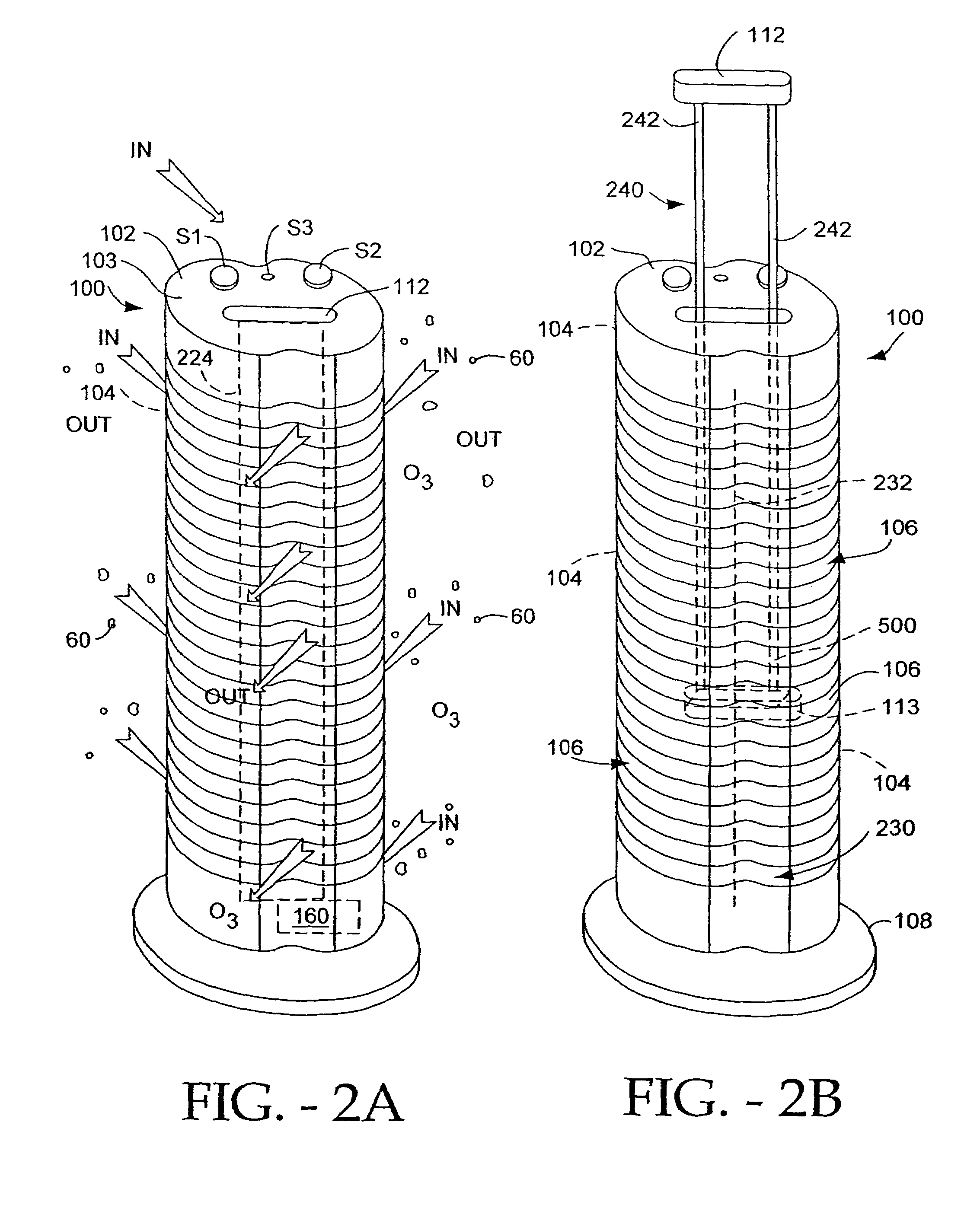
FIGS. 2A-2B

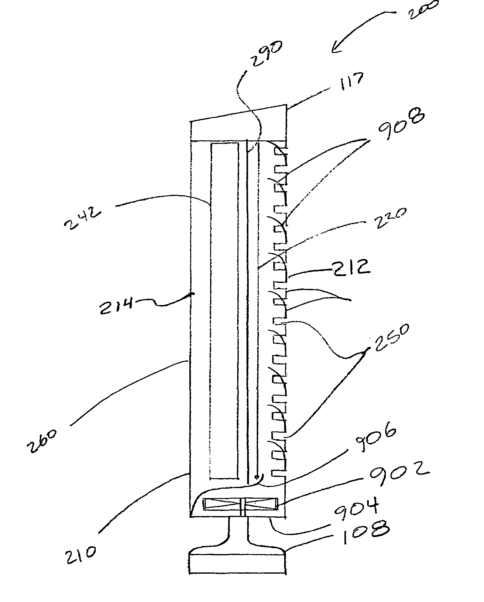
[0069]FIGS. 2A-2B depict a system which does not have incorporated therein a germicidal lamp. However, these embodiments do include other aspects such as the removable second electrodes which can be included in the other described embodiments.

[0070]FIGS. 2A and 2B depict an electro-kinetic air transporter-conditioner system 100 whose housing 102 includes preferably rear-located intake vents or louvers 104 and preferably front-located exhaust vents 106, and a base pedestal 108. Preferably, the housing 102 is freestanding and / or upstandingly vertical and / or elongated. Internal to the transporter housing 102 is an ion generating unit 160, preferably powered by an AC:DC power supply that is energizable or excitable using switch S1. Switch S1, along with the other below-described user operated switches, is conveniently located at the top 103 of the unit 100. Ion generating unit 160 is self-contained in that other than amb...


PUM

PropertyMeasurementUnit
wavelengthaaaaaaaaaa
widthaaaaaaaaaa
widthaaaaaaaaaa

Abstract

An air transporter-conditioner device is disclosed that can include an elongated housing having a bottom, a top and an elongated side wall. The housing can have an inlet located adjacent to the bottom and an outlet located adjacent to the elongated side wall, an emitter electrode and a collector electrode and a high voltage generator operably connected to both electrodes. An impeller can be used to draw air into the housing through the inlet and direct the air toward the outlet. The housing can also include a second elongated side wall and a baffle which can include a plurality of deflectors positioned along the second elongated side wall. The baffle can include a plurality of elongated columns of varying lengths and each column can include a deflector. The device can further include a second inlet located adjacent to the elongated side wall and a germicidal lamp located inside the elongated housing.

Description

CLAIM OF PRIORITY[0001]This application claims priority to U.S. Provisional Patent Application No. 60 / 538,973, filed Jan. 22, 2004, and is a continuation-in-part of U.S. patent application Ser. No. 10 / 074,096, filed Feb. 12, 2002, now U.S. Pat. No. 6,974,560, which claims priority to U.S. Provisional Patent Application No. 60 / 341,179, filed Dec. 13, 2001, and to U.S. Provisional Patent Application No. 60 / 306,479, filed Jul. 18, 2001, which is a continuation-in-part of U.S. patent application Ser. No. 09 / 774,198, filed Jan. 29, 2001, now U.S. Pat. No. 6,544,485, which is a continuation-in-part of U.S. patent application Ser. No. 09 / 924,624, filed Aug. 8, 2001, now abandoned which is a continuation of U.S. patent application Ser. No. 09 / 564,960, filed May 4, 2000, now U.S. Pat. No. 6,350,417, which is a continuation-in-part of U.S. patent application Ser. No. 09 / 186,471, filed Nov. 5, 1998, now U.S. Pat. No. 6,176,977. Priority is claimed to each of the applications recited above and ...

Claims


Application Information

Patent Timeline
Patent Type & Authority Patents(United States)
IPC IPC(8): B03C3/016B03C3/36
CPCB03C3/32B03C3/363B03C3/365B03C3/366B03C3/68B03C2201/14B03C2201/28
Inventor TAYLOR, CHARLES E.PARKER, ANDREW J.
Owner SHARPER IMAGE ACQUISITION LLC A DELAWARE LIMITED LIABILITY
Why Eureka
Try Eureka