

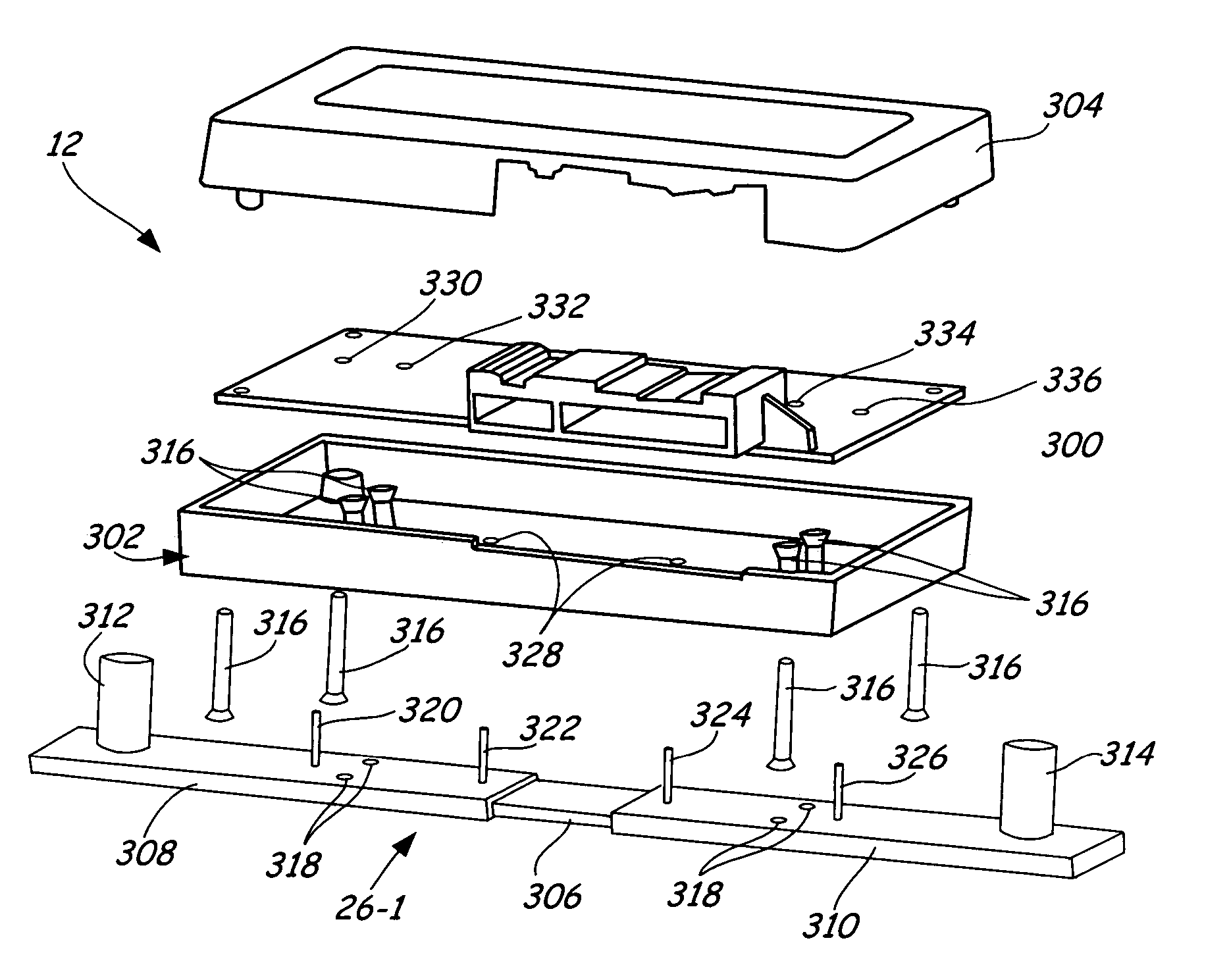
Shunt connection to a PCB of an energy management system employed in an automotive vehicle
a technology of energy management system and shunt, which is applied in the direction of emergency protective circuit arrangement, emergency protection arrangement for limiting excess voltage/current, testing electric installations on transport, etc., can solve the problem of complex technique for connecting the shunt to the pcb
- Summary
- Abstract
- Description
- Claims
- Application Information
AI Technical Summary
Problems solved by technology
Method used
Image

Examples
Embodiment Construction
[0017]The present invention offers a technique for a coupling a shunt (utilized for current measurement) to a printed circuit board (PCB) of an energy management system employed in an automotive vehicle. The technique includes utilizing flexible electrical connectors to couple the shunt to the PCB of the energy management system. This allows for shunt expansion and contraction, due to temperature changes, while maintaining connection to the PCB. To provide a clear understanding of the present invention, the energy management system, with its components, is first described. Thereafter, details regarding connecting the shunt to the PCB of the energy management system are provided. It should be noted that, for simplification, the energy management system PCB has been excluded from figures that do not explicitly show techniques for coupling the shunt to the PCB.
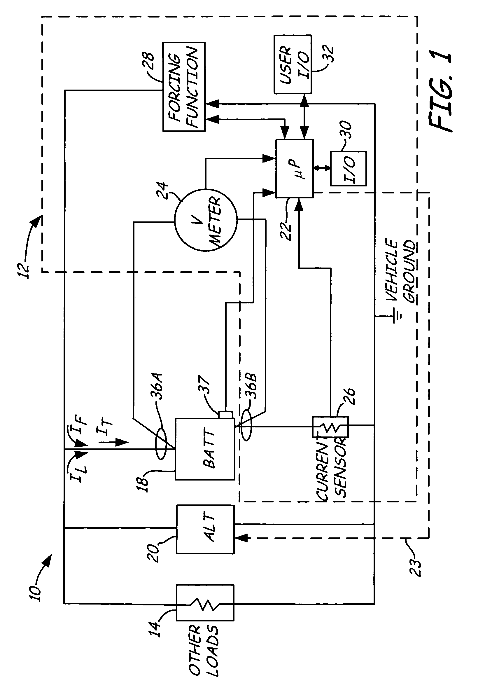
[0018]FIG. 1 is a simplified block diagram showing an automotive vehicle 10, which includes a battery monitor or energy managem...
PUM
| Property | Measurement | Unit |
|---|---|---|
| open-circuit voltage | aaaaa | aaaaa |
| voltage | aaaaa | aaaaa |
| flexible | aaaaa | aaaaa |
Abstract
Description
Claims
Application Information