Fluid and laser system

a laser system and laser technology, applied in the field of medical cutting, can solve the problems of mechanical cutting force imparted onto the tissue and explosion of atomized particles

Inactive Publication Date: 2008-01-22
BIOLASE TECH INC
View PDF84 Cites 59 Cited by
  • Summary
  • Abstract
  • Description
  • Claims
  • Application Information

AI Technical Summary

Benefits of technology

[0012]The fluid conditioning system of the present invention is adaptable to most existing medical and dental cutting, irrigating, evacuating, cleaning, and drilling apparatuses. Flavored fluid is used in place of regular tap water during drilling operations. In the case of a laser surgical operation, electromagnetic energy is focused in a direction of the tissue to be cut, and a fluid router routes flavored f

Problems solved by technology

This absorption of the electromagnetic energy by the atomized particles causes the

Method used


Image

  • Fluid and laser system
  • Fluid and laser system
  • Fluid and laser system

Examples


Embodiment Construction

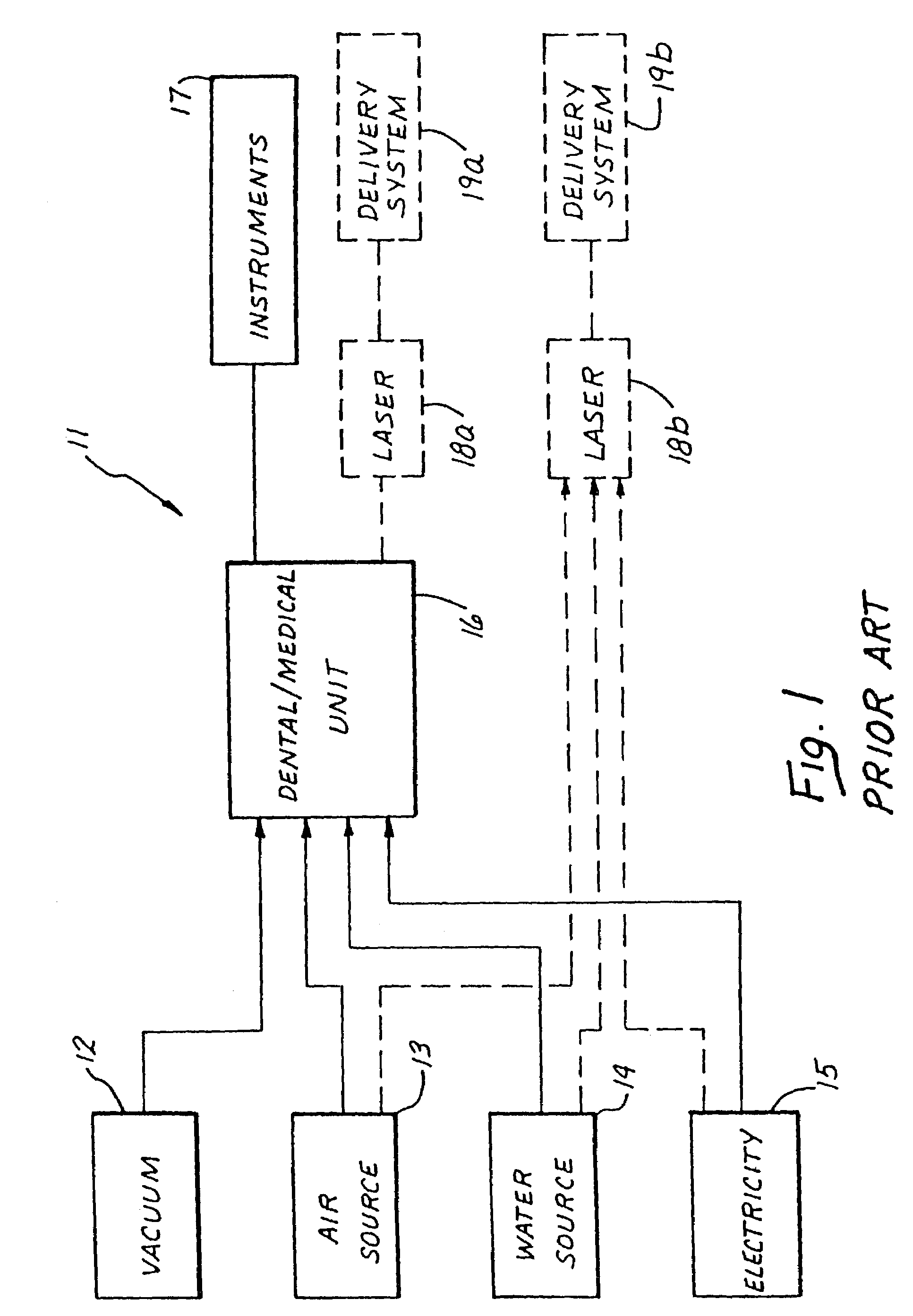
[0031]The dental / medical work station 111 of the present invention is shown in FIG. 3, with elements similar to those shown in FIG. 1 proceeded by a “1”. The dental / medical work station 111 comprises a conventional air line 113 and a conventional water line 114 for supplying air and water, respectively. A vacuum line 112 and an electrical outlet 115 supply negative air pressure and electricity to the dental / medical unit 116, similarly to the vacuum 12 and electrical 15 lines shown in FIG. 1. The fluid conditioning unit 121 may, alternatively, be placed between the dental / medical unit 116 and the instruments 117, for example. According to the present invention, the air line 113 and the water line 114 are both connected to a fluid conditioning unit 121.

[0032]A controller 125 allows for user inputs, to control whether air from the air line 113, water from the water line 114, or both, are conditioned by the fluid conditioning unit 121. A variety of agents may be applied to the air or wa...


PUM

PropertyMeasurementUnit
Wavelengthaaaaaaaaaa
Forceaaaaaaaaaa

Abstract

A fluid conditioning system is adapted to condition the fluid used in medical and dental cutting, irrigating, evacuating, cleaning, and drilling operations. The fluid may be conditioned by adding flavors, antiseptics and/or tooth whitening agents such as peroxide, medications, and pigments. In addition to the direct benefits obtained from introduction of these agents, the laser cutting properties may be varied from the selective introduction of the various agents.

Description

[0001]This application is a divisional of U.S. application Ser. No. 09 / 997,550, filed Nov. 27, 2001 (now U.S. Pat. No. 6,561,803), which is a continuation of U.S. application Ser. No. 09 / 256,697, filed Feb. 24, 1999 (now U.S. Pat. No. 6,350,123), which is a continuation-in-part of U.S. application Ser. No. 08 / 985,513, filed Dec. 5, 1997 (now abandoned), which is a continuation of U.S. application Ser. No. 08 / 522,503, filed Aug. 31, 1995 (now U.S. Pat. No. 5,741,247), the contents of all which are expressly incorporated herein by reference. This application is also a continuation-in-part of U.S. application Ser. No. 08 / 995,241, filed Dec. 17, 1997 (now abandoned), which is a continuation of U.S. application Ser. No. 08 / 575,775, filed Dec. 20, 1995 (now U.S. Pat. No. 5,785,521), the entire contents of both which are expressly incorporated herein by reference.BACKGROUND OF THE INVENTION[0002]The present invention relates generally to medical cutting, irrigating, evacuating, cleaning, a...

Claims


Application Information

Patent Timeline
IPC IPC(8): A61C3/00A61B17/16A61B17/22A61B17/32A61B18/00A61B18/20A61B18/26A61B19/00A61C1/00A61F2/00A61M3/02B23K26/14
CPCA61B18/201A61B18/26A61C1/0007A61C1/0046A61C1/0061A61C17/02A61C17/0202A61C17/0208A61C17/0217B23K26/1411B23K26/1417A61B17/16A61B17/3203A61B18/20A61B2017/22085A61B2018/00011A61B2018/00017A61B2018/00029A61B2018/1807A61B2019/4868A61B2218/005A61B2218/008A61C2201/007A61F2210/0014A61M3/0279A61N2005/0644B23K26/144B23K26/146A61B2090/0813
Inventor RIZOIU, IOANA M.KIMMEL, ANDREW I.
Owner BIOLASE TECH INC
Why Eureka
Try Eureka