Cervical interbody device

a cervical interbody and cervical technology, applied in the field of cervical interbody devices, can solve the problems of difficult to fill the spacer with such bone tissue, difficult to install the spacer between existing vertebrae, and difficult to fill the spacer with additional bone tissu

Inactive Publication Date: 2008-01-22
WARSAW ORTHOPEDIC INC
View PDF63 Cites 215 Cited by
  • Summary
  • Abstract
  • Description
  • Claims
  • Application Information

AI Technical Summary

Benefits of technology

[0004]According to the present invention, a spacer assembly is provided for use in spinal surgeries. The spacer assembly comprises two end pieces for interfacing with the end plates of adjacent vertebrae. Each end piece is generally disk-like in form and includes an inner surface facing the interior of the spacer and an outer surface facing the adjacent vertebrae. Each end piece has attached thereto a flange that extends longitudinally and exteriorly of the end piece. The end pieces are spaced and reinforced by one or more connectors. The spacer assembly engages the adjacent vertebral disks by engaging each flange with the adjacent vertebrae to couple the assembly and vertebrae together. The spacer assembly defines an interior region that is filled with morselized bone graft, structural bone graft, biologic fusion materials, or solid bone to fuse together and with the adjacent vertebrae, thereby replacing pathological bone or disk material removed surgically.

Problems solved by technology

The prior art spacers are difficult to install between existing vertebrae and difficult to satisfactorily fill with such bone tissue.
The granular bone tissue placed within the mesh tends to fall out of the mesh during the positioning process, and the mesh makes it difficult to refill the spacer with additional bone tissue.
Gaps between the bone tissue inside the cage often result, which cannot be readily detected or remedied.
Consequently, the grafting process is slowed or results in a weakened graft or incomplete fusion and malalignment due to these gaps.

Method used


Image

  • Cervical interbody device
  • Cervical interbody device
  • Cervical interbody device

Examples


Embodiment Construction

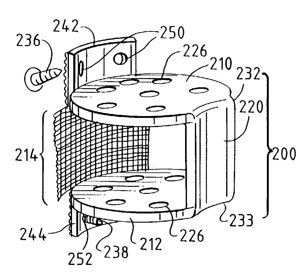
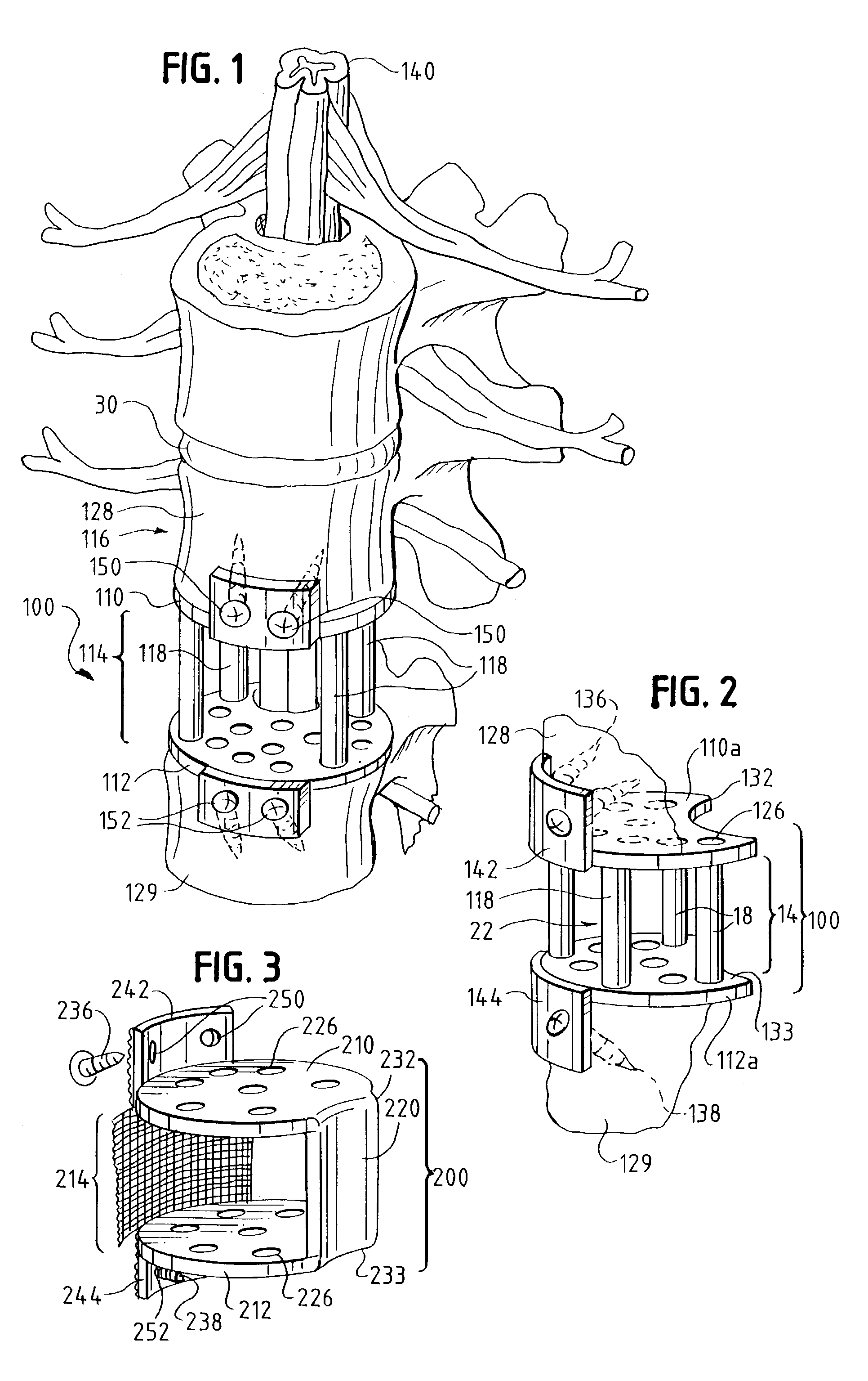
[0015]As seen in FIGS. 1, 2, the inventive spacer assembly 100 includes an upper end piece 110 and a lower end piece 112 with connector 118 therebetween. The assembly 100 is located between the vertebral bodies of a spine 116 during surgery to maintain the vertebrae in a spaced-apart configuration. End pieces 110, 112 of the present invention are substantially parallel to the adjoining surfaces (often referred to as “end plates”) of the vertebral bodies 128, 129 and are shaped and dimensioned to closely match the cross-sectional shape and dimensions of the end plates.

[0016]Connectors 118 comprise one or more rigid or semi-rigid posts for maintaining a desired distance between the end pieces 110, 112. For example, titanium posts 118, as seen in FIGS. 1 and 2, maintain the spacing between the end pieces so that granular bone material can be inserted between the end pieces in the interior region 114 defined by the assembly 100. The connectors 118 may be of equal length or they may be o...


PUM


Abstract

An interbody spacer assembly includes a pair of end pieces spaced apart by a connector extending between them. The end pieces extend generally parallel to the end plates of adjoining vertebral bodies. Fasteners connect the end pieces to the vertebral bodies. Bone graft material or solid bone can be placed in the interior space defined by the end pieces and connector, which bone graft material or solid bone eventually fuses together and to the adjoining end plates through the end pieces.

Description

[0001]This invention relates to cervical spine supports, and, in particular, to a device that acts as a spacer between cervical vertebral bodies so that bone graft material inserted within the device can fuse and replace pathological bone removed surgically.BACKGROUND OF THE INVENTION[0002]It is known in the prior art to use cage-like spacers made of titanium mesh in tube shapes between vertebrae to provide support to the cervical spine. Spacers are needed when either the vertebrae or disk are removed for pathological reasons due to injury or disease. One such spacer 10 is shown in FIGS. 6 and 7. Such prior art spacers are typically formed from a mesh 12 rolled into a tube extending longitudinally for the length of the removed vertebrae or disk. Rings 14 on both ends 16, 18 are intended to reinforce the mesh and maintain the desired diameter of the spacer and also connect to adjacent vertebrae with screws 20. Spacer 10 is filled with granular bone tissue which eventually fuse or gra...

Claims


Application Information

Patent Timeline
Patent Type & Authority Patents(United States)
IPC IPC(8): A61F2/44A61F2/30
CPCA61F2/44A61F2/4465A61F2/30907A61F2002/2835A61F2002/2839A61F2002/30131A61F2002/30571A61F2002/30616A61F2002/30772A61F2002/30904A61F2002/30909A61F2230/0013A61F2310/00023
Inventor BERNSTEIN, AVI
Owner WARSAW ORTHOPEDIC INC
Why Eureka
Try Eureka