
Electronic insertion/extraction cycle counter and logger device

Inactive Publication Date: 2008-01-22
TELLABS OPERATIONS
View PDF10 Cites 39 Cited by
  • Summary
  • Abstract
  • Description
  • Claims
  • Application Information

AI Technical Summary

Benefits of technology

[0002]The present invention addresses the connector wear problem by monitoring insertions or extractions associated with wear of the connector. Accordingly, a monitoring system of the present invention includes a sensor and a monitor. The sensor may sense insertions or extractions through contact sensors, e.g., through a spare pin or a mechanical

Problems solved by technology

Over time, the connector's sockets wear out and the electrical connection between any given circuit board and the test interface degrades.
The effects on testing are detrimental.
Instead of detecting failures in a circuit board product, the testing interface may incorrectly detect a failure as a result of a poor electrical or optical connection in a connector.
As a result, manufacturers suffer from decreased yield when they discard circuit boards that fail testing procedures because of a poor electrical connection.
In other applications, systems or networks may experience failures due to regular maintenance of the systems that includes unplugging and re-plugging circuit boards or cables.

Method used


Image

  • Electronic insertion/extraction cycle counter and logger device
  • Electronic insertion/extraction cycle counter and logger device
  • Electronic insertion/extraction cycle counter and logger device

Examples


Embodiment Construction

[0017]A description of preferred embodiments of the invention follows.

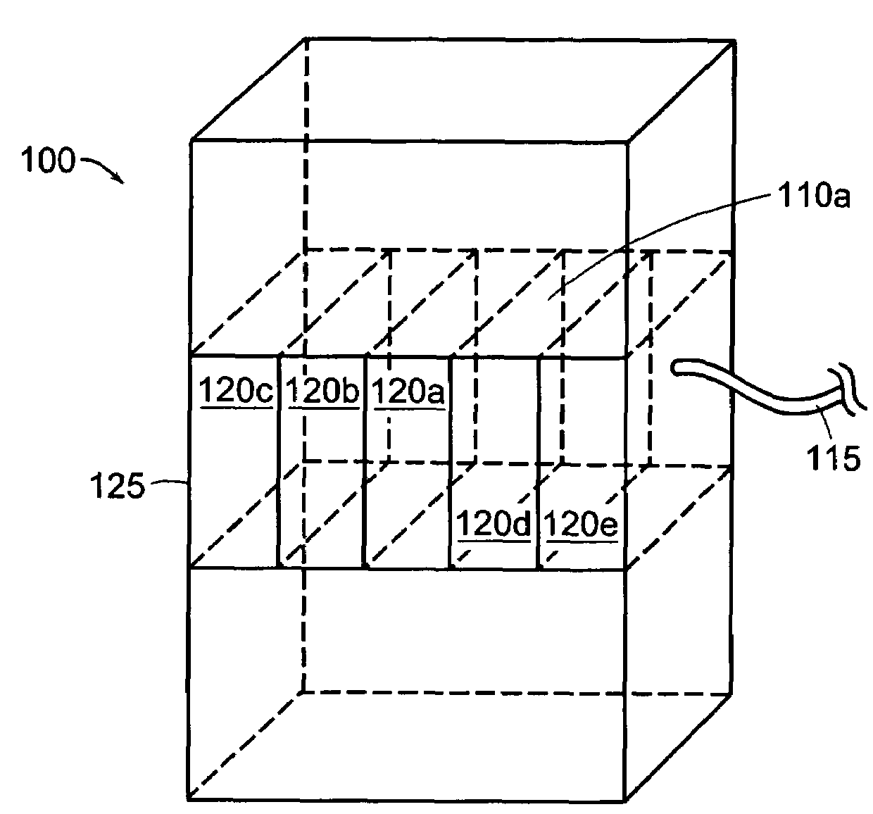
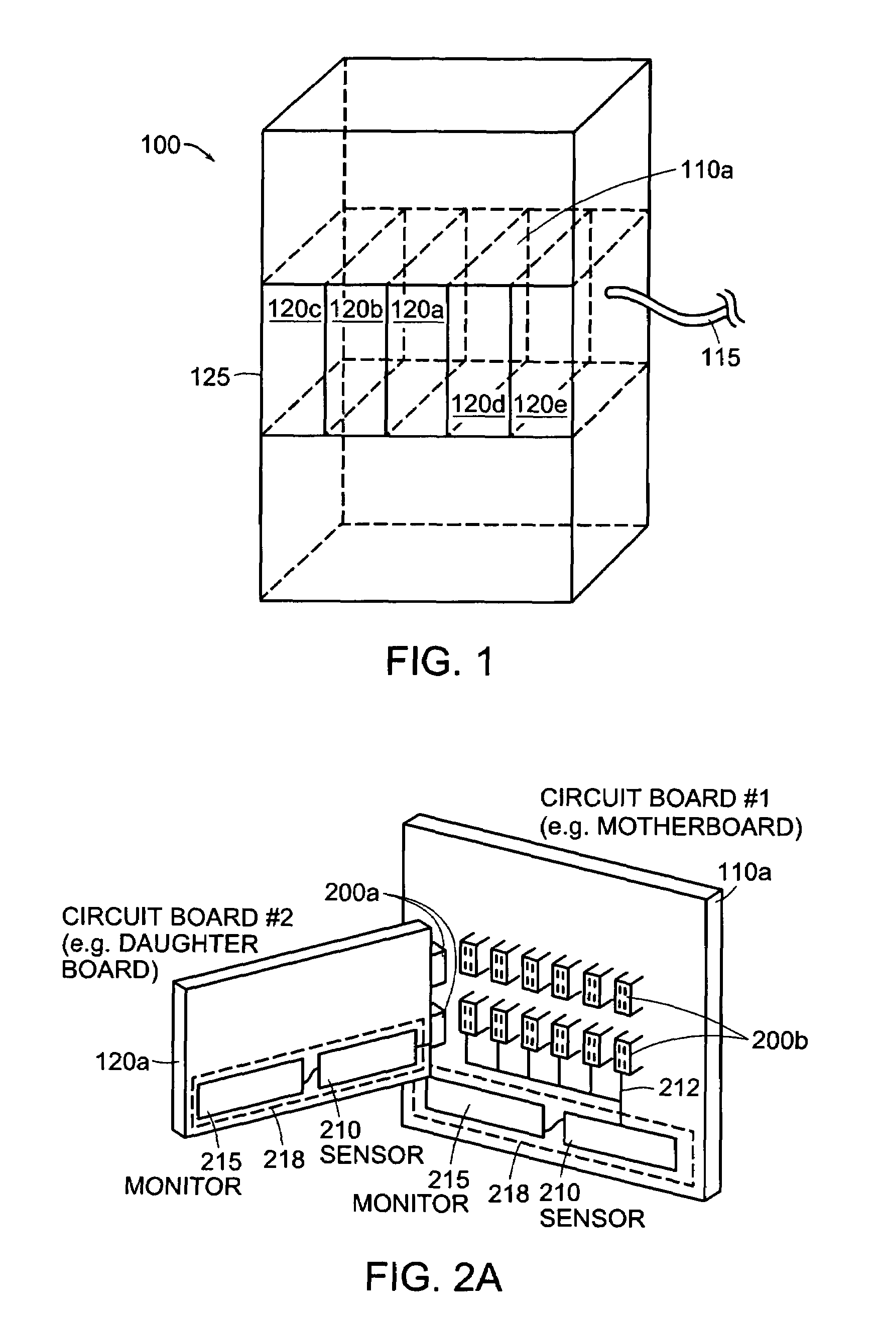
[0018]FIG. 1 illustrates an electronics system 100 that includes an electronics rack or shelf 125 of circuit boards 120a, 120b, . . . , 120e (collectively circuit boards 120). The electronics shelf 125 is assembled in part by inserting a second circuit board 120a into a first circuit board 110a. In other systems, such as desktop computers or circuit board test systems, the circuit board 120a is referred to as a daughter board 120a, and the backplane 110a may be a motherboard 110a.

[0019]In each case, a connector (not shown), such as a 64-pin or 96-pin DIN connector, is attached to each circuit board 110a and 120a. More specifically, a first part of a connector is attached to one circuit board 120a and a second part of the connector is attached to the other circuit board 110a. Other circuit boards 120b-120e connect to the backplane 110a in a similar manner.

[0020]Connectors are also found on cables, such as a cable ...


PUM


Abstract

A monitoring system monitors wear of a connector by counting insertions or extractions between circuit boards. The monitoring system includes a sensor that senses insertions or extractions through contact or non-contact sensing. The monitoring system also includes a monitor connected to the sensor to monitor insertions or extractions and, optionally, store data in memory and generate an alarm signal if a predetermined threshold has been exceeded. The monitoring system may be positioned at any location in an electronic system and may be configured such that the sensor connects to the monitor directly, indirectly, or over a network.

Description

BACKGROUND OF THE INVENTION[0001]Many electronic systems are assembled through the use of electrical or optical connectors, such as circuit board to circuit board connectors, cable to circuit board connectors, and cable to cable connectors. Connectors typically include a plug part and socket part, which interconnect. In certain applications, the plug part of the connector is inserted and extracted many times from the socket part of the connector. For example, when testing a circuit board product, a manufacturer inserts and extracts many circuit boards from a single test interface connector. Over time, the connector's sockets wear out and the electrical connection between any given circuit board and the test interface degrades. The effects on testing are detrimental. Instead of detecting failures in a circuit board product, the testing interface may incorrectly detect a failure as a result of a poor electrical or optical connection in a connector. As a result, manufacturers suffer fr...

Claims


Application Information

Patent Timeline
IPC IPC(8): G08B21/00
CPCH01R13/641H01R23/6873H05K7/1452H05K7/1459H01R9/096H01R13/6683H01R2201/20H01R12/52H01R13/658
Inventor INLOW, MARK C.
Owner TELLABS OPERATIONS
Learn More