Check patentability & draft patents in minutes with Patsnap Eureka AI!

Print job managing apparatus and print job control method

a technology of managing apparatus and printing job, applied in the direction of digital output to print unit, digitally marking record carrier, instruments, etc., can solve the problem of not being able to control the job

Inactive Publication Date: 2008-01-22
MATSUSHITA GRAPHIC COMM SYST INC
View PDF14 Cites 93 Cited by
  • Summary
  • Abstract
  • Description
  • Claims
  • Application Information

AI Technical Summary

Benefits of technology

[0007]This invention is provided to address the above described problems. The object of the present invention is to provide a print job managing apparatus and print job control method that is easy to use, eliminating the bother of inputting a password for every print job control and enabling a terminal to control only the print jobs performed by the particular terminal.

Problems solved by technology

When it is different, the control of the job is not allowed.

Method used


Image

  • Print job managing apparatus and print job control method
  • Print job managing apparatus and print job control method
  • Print job managing apparatus and print job control method

Examples


first embodiment

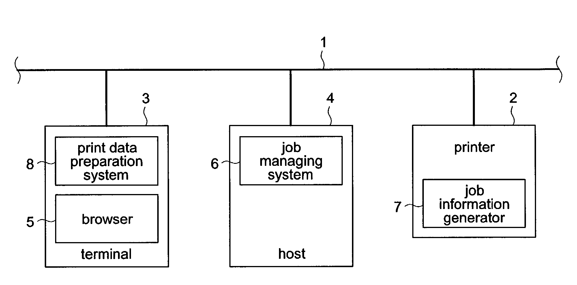
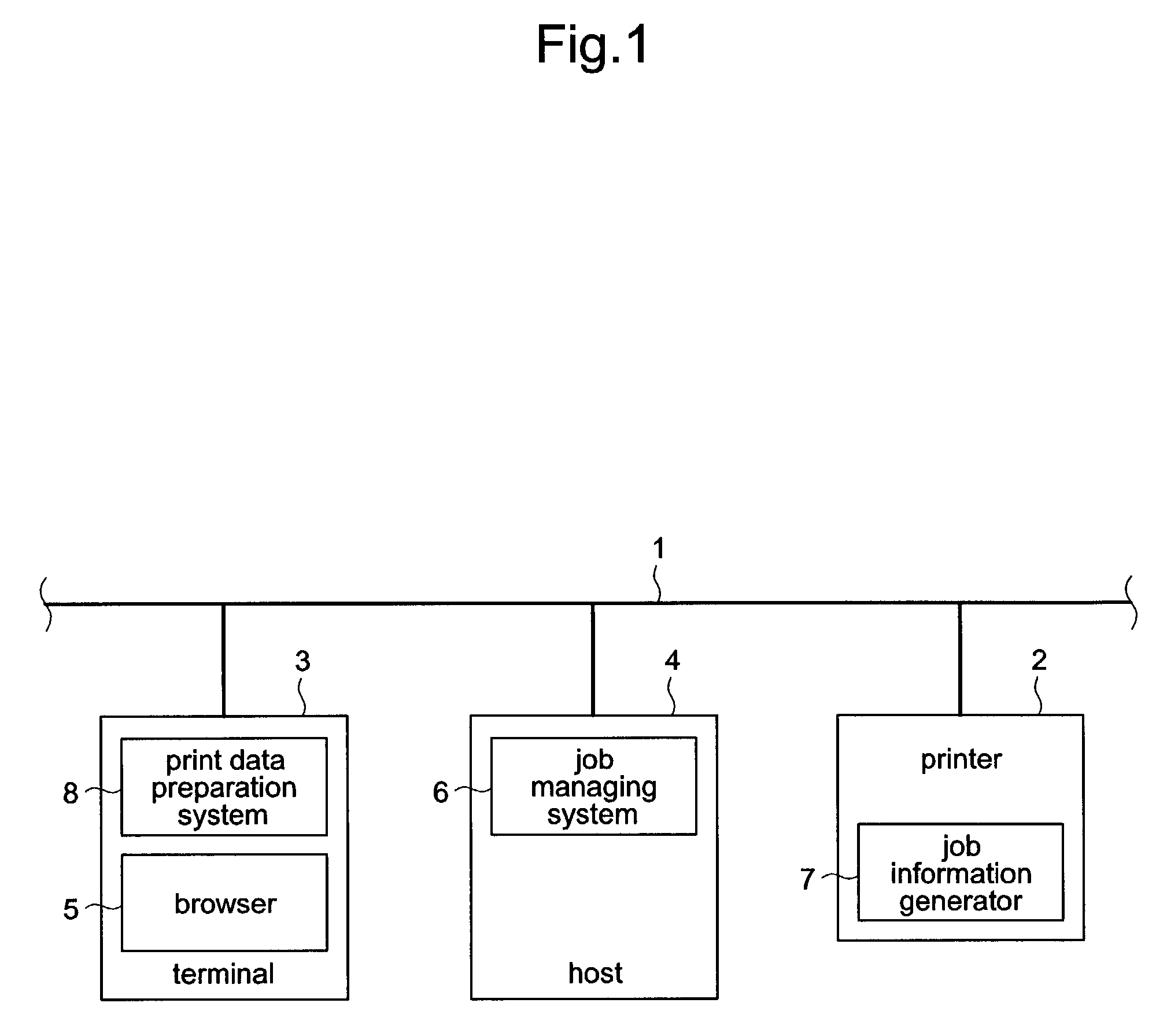
[0029]FIG. 1 illustrates a system configuration according to the first embodiment of the present invention. As shown in FIG. 1, the system includes printer 2, terminal 3 that transmits a print request to printer 2, and host 4 that manages a job spooled in printer 2 and performs a job control in response to the request from terminal 3, all of which are mutually connected for communicating via local area network (LAN) 1. Terminal 3 includes general functions to operate as a personal computer, as well as print data preparation system 8 that performs a process adding an IP address of terminal 3 to a document generated by a word processing software, and browser 5 that provides a user with a job control environment. Host 4 includes job managing system 6 that provides a later-described job control. Printer 2 includes job information generator 7 that generates job information related to print data received from terminal 3.

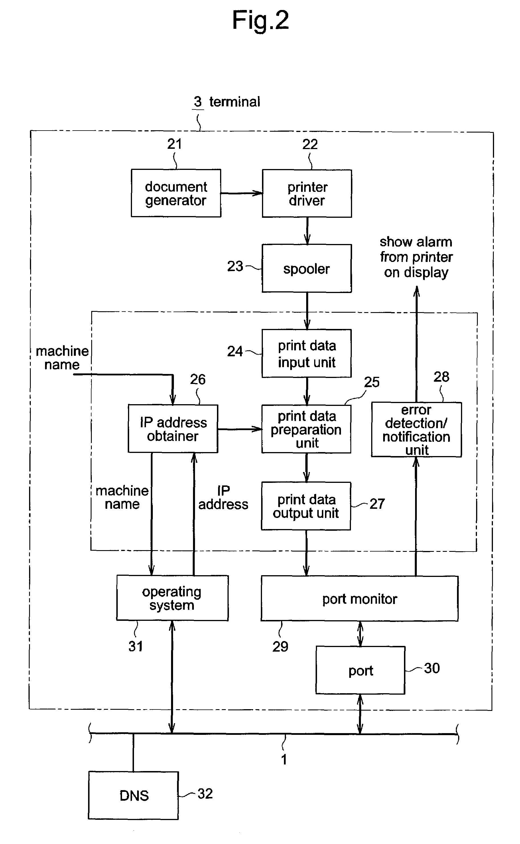
[0030]FIG. 2 is a functional block diagram relating to print data pre...

second embodiment

[0073]The following illustrates the second embodiment of the present invention. In the second embodiment, when a manager terminal makes a request for a job list display screen, the job control is not limited. Other configuration and operation are the same as the first embodiment.

[0074]FIG. 15 is a block diagram illustrating a configuration of job managing system 6 at host 4. In FIG. 15, parts having the same numerical characters as the block diagram of job managing system 6 of FIG. 3 represent the same function; therefore the illustration of the same is omitted.

[0075]In the second embodiment, job managing system 6 is provided with manger registration unit 501 that receives a manager registration and stores the manager information, and manager determiner 502 that determines whether the accessing terminal is the manger terminal. HTML file generator 42 uses the determination result from manager determiner 502 and switches contents of the generated job list display screen.

[0076]First, t...


PUM


Abstract

A host that controls jobs of a printer obtains client identifying information within a job control request, which is received from a terminal, while obtaining the job information and client identifying information of the print request from the printer, and storing the same in a job information storage unit. For each job included in the job information that is obtained from the printer, a job control capability determiner compares the client identifying information (of print requester) and client identifying information of the terminal that made a control request. When both of the client identifying information is identical, it is determined that the control is allowed. When it is not identical, it is determined that the control is not allowed.

Description

BACKGROUND OF THE INVENTION[0001]1. Field of the Invention[0002]The present invention relates to a print job managing apparatus and print job controlling method that can control a spooled print job in a printer connected to a network, from a client computer (hereafter referred to as “terminal”).[0003]2. Description of Related Art[0004]Conventionally, print job managing systems have been introduced that can control (e.g., delete) a spooled print job in the printer connected to a network, from a terminal via the network. Such print job managing system are configured so that a printing job spooled in a printer is controlled from a host computer (hereafter referred to as “host”). When a control request is made to a host from a terminal, which is requesting a print job control, whether the terminal has permission for a job control is checked, from a password input at the terminal. Upon confirming the permission, the host receives the request, e.g., deleting / prioritizing of a print job, a...

Claims


Application Information

Patent Timeline
IPC IPC(8): G06F3/12B41J29/38
CPCG06K15/007G06K15/1806G06F3/1204G06F3/1224G06F3/1259G06F3/126G06F3/1285G06F3/1222G06F3/1238
Inventor KIMURA, SHOUGO
Owner MATSUSHITA GRAPHIC COMM SYST INC
Features
  • R&D
  • Intellectual Property
  • Life Sciences
  • Materials
  • Tech Scout
  • Unparalleled Data Quality
  • Higher Quality Content
  • 60% Fewer Hallucinations
Learn More