Communication device with smart antenna using a quality-indication signal

a communication device and quality indicator technology, applied in the field of communication, can solve the problems of limited power-control signaling use, limited bandwidth per information channel, and limited serviceability of users,

Active Publication Date: 2008-01-22
GOOGLE LLC
View PDF68 Cites 98 Cited by
  • Summary
  • Abstract
  • Description
  • Claims
  • Application Information

AI Technical Summary

Problems solved by technology

Broadband networks having multiple information channels are subject to certain types of typical problems such as inter-channel interference, a limited bandwidth per information channel, inter-cell interference that limit the maximum number of serviceable users, and other interference.
The known uses of power-control signaling have been limited only to adjusting the total power of the signal transmitted from the communication device.

Method used


Image

  • Communication device with smart antenna using a quality-indication signal
  • Communication device with smart antenna using a quality-indication signal
  • Communication device with smart antenna using a quality-indication signal

Examples


Embodiment Construction

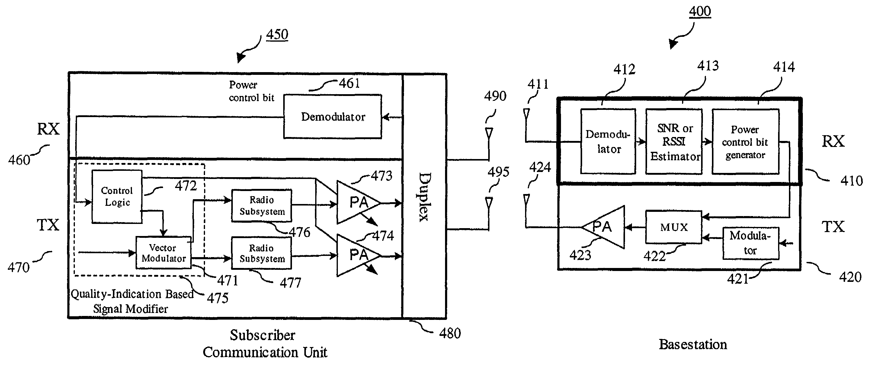
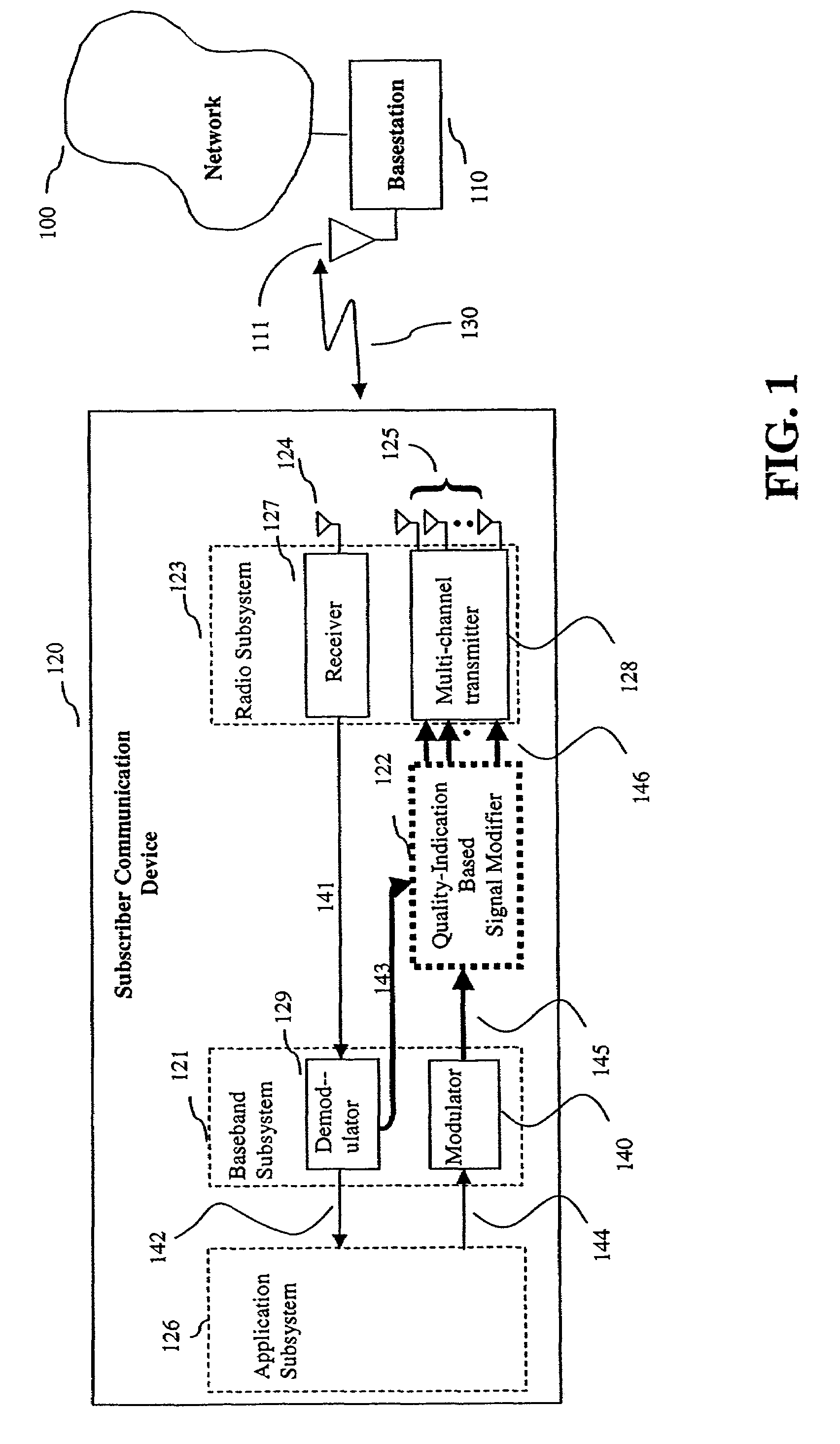
[0021]A transmitted signal sent from a subscriber communication device to a second communication device (e.g., a basestation) can be weakened by time or by propagation-geometry-dependent fading and multipath. In other words, a signal sent from a subscriber communication device to a basestation will undergo destructive interference due to the fact that the transmitted signal propagates along different paths and reaches the basestation as a combination of the signals each having a different phase.

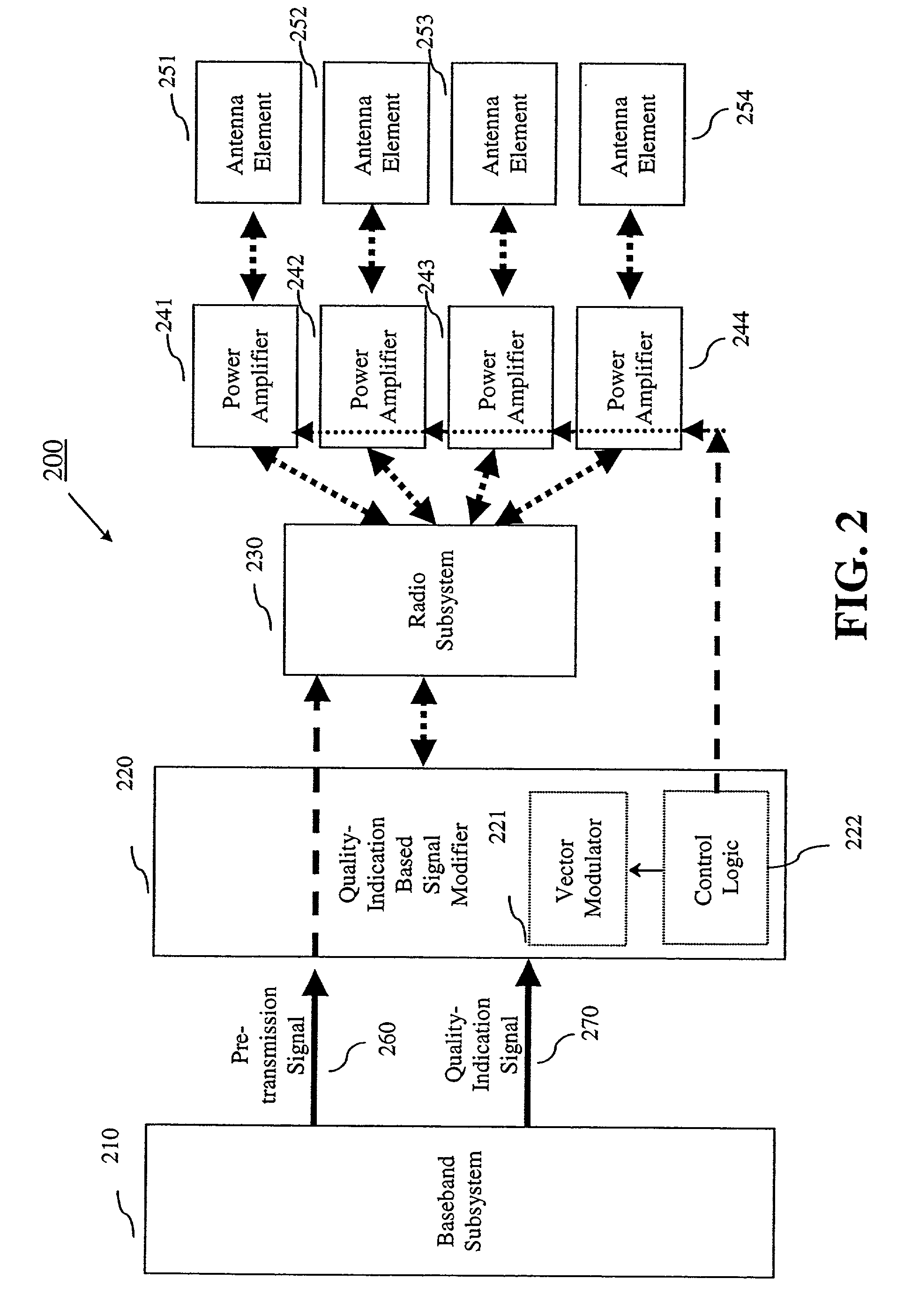
[0022]Accordingly, by controlling the phase of the transmitted signal at the subscriber communication device, the combination of signals received at the basestation can constructively interfere rather than destructively interfere, or alternatively reduce the intensity of the destructive interference. The phase of the transmitted signal can be controlled through the use of multiple antenna elements at the subscriber communication device. If the rate at which the transmitted signal is controlle...


PUM


Abstract

Communication is performed for a first communication device having a set of antenna elements. A quality-indication signal is received from a second communication device. A complex weighting is calculated based on the quality-indication signal. A pre-transmission signal is modified based on the complex weighting to produce a set of modified-pre-transmission signals. Each modified pre-transmission signal from the set of modified-pre-transmission signals is uniquely associated with an antenna element from the set of antenna elements. The set of modified-pre-transmission signals is sent from the set of antenna elements to produce a transmitted signal.

Description

CROSS-REFERENCE TO RELATED APPLICATIONS[0001]This application claims priority to now abandoned U.S. Provisional Patent Application No. 60 / 294,290, entitled “Smart Antennae: Using Standard Power Control Signaling On Cellular Systems For Smart Antenna Control within Cell Phone,” filed on May 31, 2001, the entirety of which is incorporated herein by reference.[0002]This application is also related to co-pending U.S. patent application Ser. No. 10 / 082,351, entitled “Smart Antenna Based Spectrum Multiplexing Using a Pilot Signal,” filed on Feb. 26, 2002, the entirety of which is incorporated herein by reference.BACKGROUND[0003]The invention relates generally to communications and more particularly to a system and method for using a quality-indication signal added to a transmitted signal in a communication system, and used by the receiving end, in conjunction with multiple antenna elements. The receiver can use a separation process known as spatial filtering, or also referred to herein as...

Claims


Application Information

Patent Timeline
Patent Type & Authority Patents(United States)
IPC IPC(8): H04L27/00H04B1/02H04B7/00H04L1/02H04B1/707H04B7/005H04B7/06H04B7/10H04B7/26H04J13/00
CPCH04B7/0623H04B7/0632H04W52/221H04W52/42H04W52/16H04W52/34H04W52/22H04B7/06
Inventor HAREL, HAIMLI, YINGXUESEGALOVITZ, ALEXANDER
Owner GOOGLE LLC
Why Eureka
Try Eureka