Variable valve apparatus and methods

a valve and valve body technology, applied in the field of variable valve apparatus and methods, can solve the problems of fluid transfer between different features of the device, transfer process, potential errors, complex and associated high costs

Inactive Publication Date: 2008-01-29
DIASORIN ITALIA SPA
View PDF91 Cites 65 Cited by
  • Summary
  • Abstract
  • Description
  • Claims
  • Application Information

AI Technical Summary

Benefits of technology

[0001]Sample processing devices including process chambers in which various chemical or biological processes are performed play an increasing role in scientific and / or diagnostic investigations. The process chambers provided in such devices are preferably small in volume to reduce the amount of sample material required to perform the processes.
[0006]The openings in the valve septum may be formed at locations based on one or more characteristics of the sample material detected within the process chamber. It may be preferred that the process chambers include detection windows that transmit light into and / or out of the process chamber. Detected characteristics of the sample material may include, e.g., the free surface of the sample material (indicative of the volume of sample material in the process chamber). Forming an opening in the valve septum at a selected distance radially outward of the free surface can provide the ability to remove a selected volume of the sample material from the process chamber.
[0007]For sample materials that can be separated into various components, e.g., whole blood, rotation of the sample processing device may result in separation of the plasma and red blood cell components, thus allowing for selective removal of the components to, e.g., different process chambers.
[0009]The openings in the valve septums are preferably formed in the absence of physical contact, e.g., through laser ablation, focused optical heating, etc. As a result, the openings can preferably be formed without piercing the outermost layers of the sample processing device, thus limiting the possibility of leakage of the sample material from the sample processing device.

Problems solved by technology

One persistent issue associated with sample processing devices including process chambers is in the transfer of fluids between different features in the devices.
Such transfer processes suffer from a number of disadvantages including, but not limited to, the potential for errors, complexity and associated high costs, etc.

Method used


Image

  • Variable valve apparatus and methods
  • Variable valve apparatus and methods
  • Variable valve apparatus and methods

Examples


Embodiment Construction

[0020]In the following detailed description of illustrative embodiments of the invention, reference is made to the accompanying figures of the drawing which form a part hereof, and in which are shown, by way of illustration, specific embodiments in which the invention may be practiced. It is to be understood that other embodiments may be utilized and structural changes may be made without departing from the scope of the present invention.

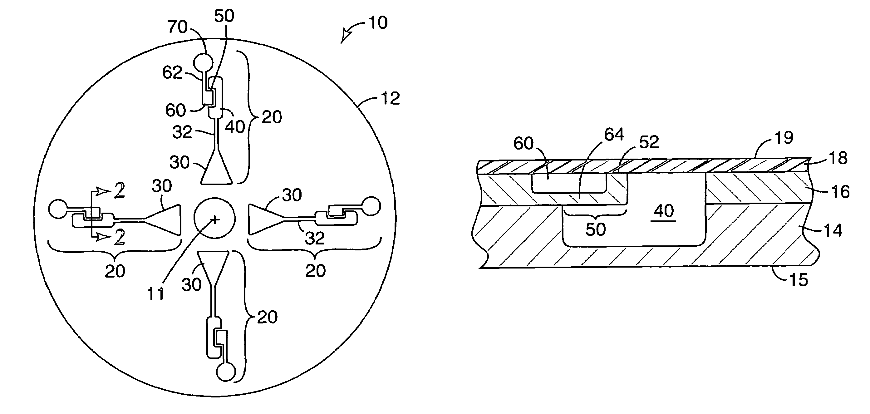
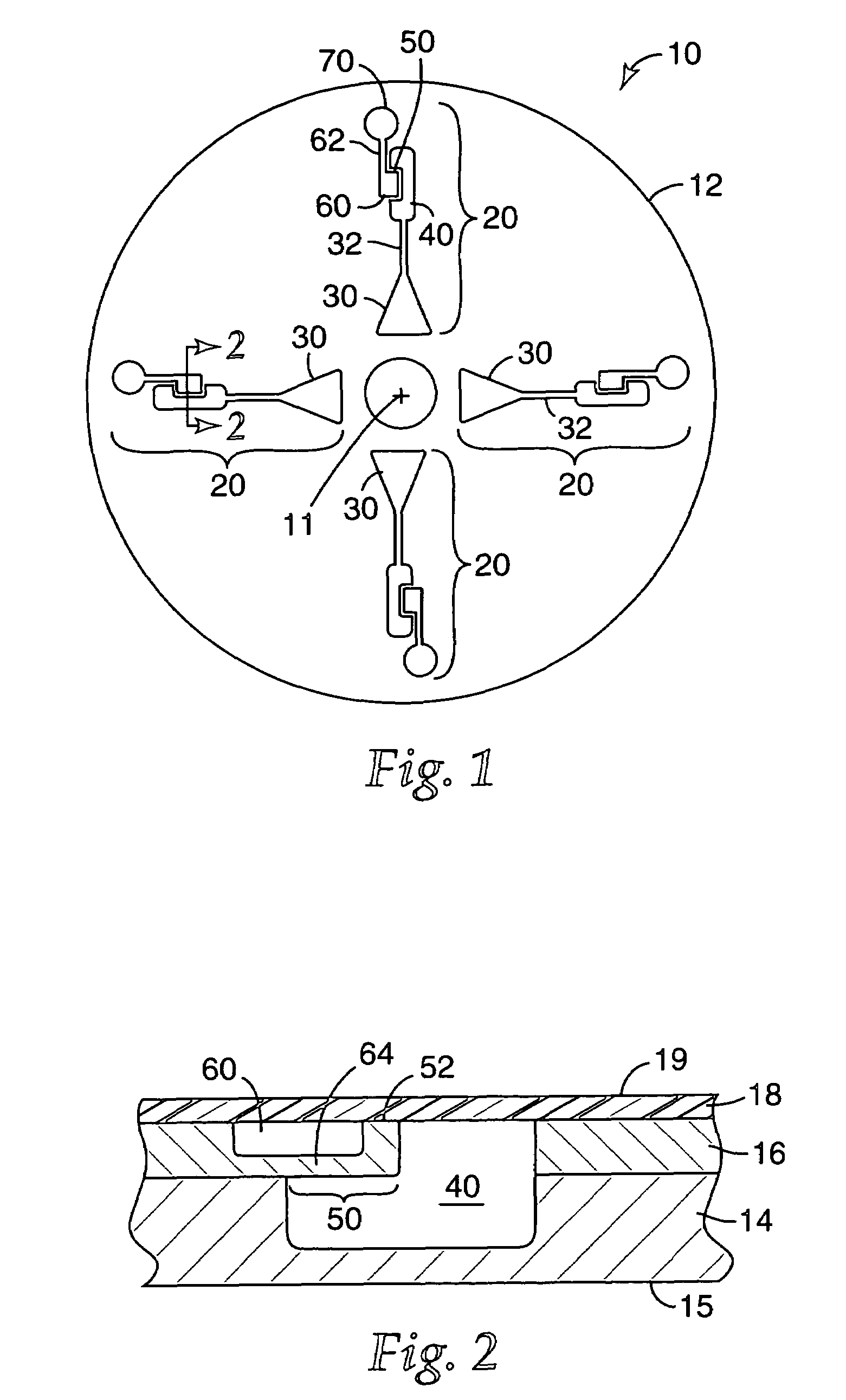
[0021]The present invention provides a sample processing device that can be used in the processing of liquid sample materials (or sample materials entrained in a liquid) in multiple process chambers to obtain desired reactions, e.g., PCR amplification, ligase chain reaction (LCR), self-sustaining sequence replication, enzyme kinetic studies, homogeneous ligand binding assays, and other chemical, biochemical, or other reactions that may, e.g., require precise and / or rapid thermal variations. More particularly, the present invention provides sample pr...


PUM

PropertyMeasurementUnit
lengthaaaaaaaaaa
lengthaaaaaaaaaa
widthaaaaaaaaaa

Abstract

Sample processing devices with variable valve structures and methods of using the same are disclosed. The valve structures allow for removal of selected portions of the sample material located within the process chamber. Removal of the selected portions is achieved by forming an opening in a valve septum at a desired location. The valve septums may be large enough to allow for adjustment of the location of the opening based on the characteristics of the sample material in the process chamber. If the sample processing device is rotated after the opening is formed, the selected portion of the material located closer to the axis of rotation exits the process chamber through the opening. The remainder of the sample material cannot exit through the opening because it is located farther from the axis of rotation than the opening.

Description

[0001]Sample processing devices including process chambers in which various chemical or biological processes are performed play an increasing role in scientific and / or diagnostic investigations. The process chambers provided in such devices are preferably small in volume to reduce the amount of sample material required to perform the processes.[0002]One persistent issue associated with sample processing devices including process chambers is in the transfer of fluids between different features in the devices. Conventional approaches to separate and transfer fluidic contents of process chambers have often required human intervention (e.g., manual pipetting) and / or robotic manipulation. Such transfer processes suffer from a number of disadvantages including, but not limited to, the potential for errors, complexity and associated high costs, etc.[0003]Attempts to address the fluid transfer issues have focused on transferring the entire fluid contents of the process chambers through, e.g...

Claims


Application Information

Patent Timeline
Patent Type & Authority Patents(United States)
IPC IPC(8): G01N1/00B01L3/00G01N1/10G01N21/01G01N21/05G01N33/49
CPCB01L3/502738G01N21/05B01J2219/00891B01L2300/0806B01L2300/0864B01L2400/0409B01L2400/0677
Inventor BEDINGHAM, WILLIAMROBOLE, BARRY W.
Owner DIASORIN ITALIA SPA
Why Eureka
Try Eureka