Aerial cable spacer with cable retaining arm having non-rectangular plus-shaped cross section and angled pawl locking member

a technology of spacer and cable, which is applied in the direction of coupling, machine support, rod connection, etc., can solve the problems of short circuit fault in grid system, prior art spacer of this type experiencing less than desirable force against the cable, and wear of the insulation on the jacketed conductor

Active Publication Date: 2008-01-29
PREFORMED LINE PROD CO
View PDF7 Cites 12 Cited by
  • Summary
  • Abstract
  • Description
  • Claims
  • Application Information

AI Technical Summary

Problems solved by technology

Insulation on jacketed conductors can be worn away and, of course, contact between uninsulated conductors would result in a short circuit fault in the grid system.
It has been found at times, however, that the prior art spacers of this type experience a less than desirable force exerted against the cables held in their respective concave seats.
In addition, in the prior devices, it was difficult to close the cable retainer with sufficient force exerted on the cable.
However, the cable retaining arm taught in the '930 patent is difficult to manufacture, adds cost to the device due to the additional materials needed to form the fulcrum point, and presents potential inherent stress and fracture areas adjacent either side of the fulcrum point section as the cable retaining arm is biased into position across the respective cable.
The resilient pad concept applied to the cable retaining arms of a spacer for aerial cables as proposed in the '783 patent adds further complexity and cost to the product and, it is believed, invites mechanical failure in the arm in the high-stress regions adjacent either side of the resilient pad.
The abutment surfaces described in the '856 patent introduce manufacturing burdens and complexities in the final product.

Method used


Image

  • Aerial cable spacer with cable retaining arm having non-rectangular plus-shaped cross section and angled pawl locking member
  • Aerial cable spacer with cable retaining arm having non-rectangular plus-shaped cross section and angled pawl locking member
  • Aerial cable spacer with cable retaining arm having non-rectangular plus-shaped cross section and angled pawl locking member

Examples


Embodiment Construction

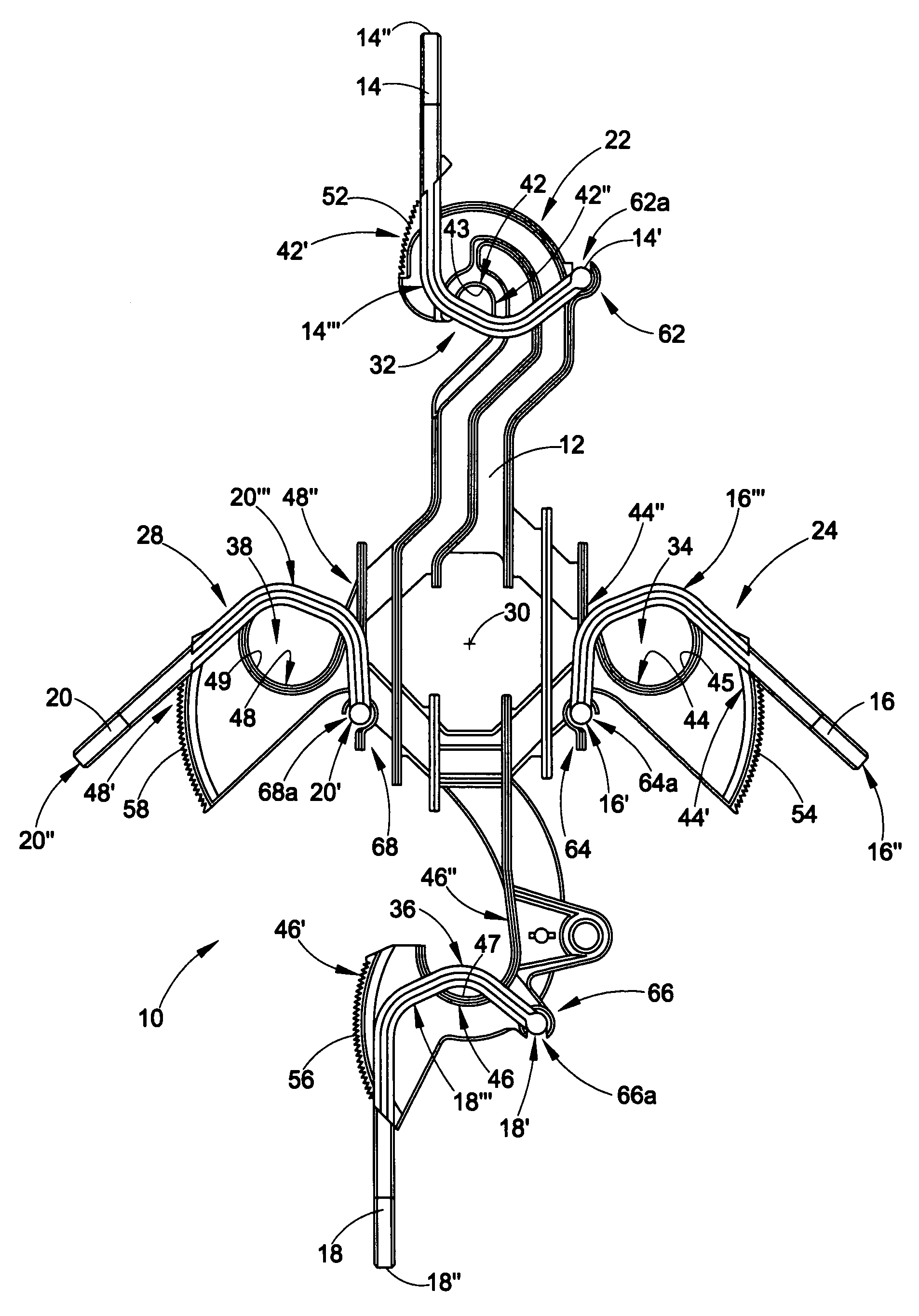
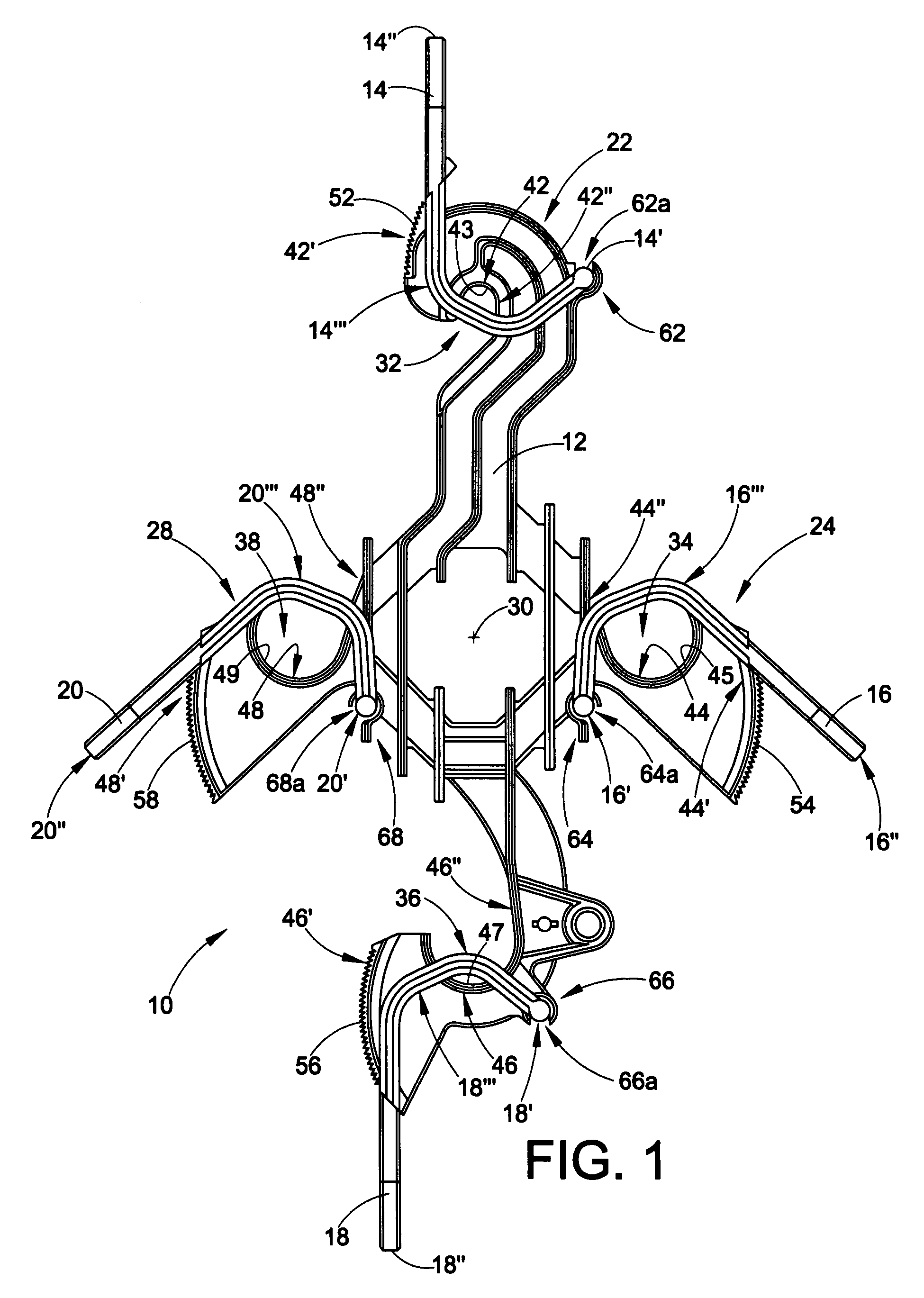
[0030]With reference now to the drawings wherein the showings are for purposes of illustrating the preferred embodiments of the invention only and not for purposes of limiting same, FIG. 1 shows an aerial cable spacer 10 including a main body member 12 and a set of generally arcuate cable retaining arms 14, 16, 18, and 20, each having a first end 14′, 16′, 18′, and 20′ pivotally connected with the main body member 12, a second end 14″, 16″, 18″, and 20″ releasably engageable with the main body member 12 in a manner to be described below, and a flexible mid portion 14″, 16″′, 18″′, and 20″′. In their preferred form, each of the cable retaining arms 14-20 are identical. In addition, both the body member and the retaining arms are made from the same thermoplastic material, preferably a resilient high-density polyethylene which has a low dielectric constant with good weather, UV, and strength characteristics. The cable retaining arms are molded separately from the body and attached ther...


PUM


Abstract

An aerial cable spacer is provided with a cable retainer and vertically disposed strengthening tabs or ribs. The cable retainer includes a cable retaining arm. A mid portion of the cable retaining arm has a non-rectangular plus “+” shaped cross section. The plus “+” shaped cross section engages and exerts a force on the cable as the cable retaining arm bends to a closed position. The arm is flexible so as to create a resilient force in conjunction with the plus “+” shaped cross section to securely hold the cable on a cable seat of a main body portion of the aerial cable spacer. A pawl is carried on the arm at a predetermined orientation to engage a corresponding set of teeth on the spacer body for enhanced cable clamping force.

Description

FIELD OF THE INVENTION[0001]The present application relates to apparatus for supporting one or more cables above the ground, and more particularly to an aerial cable spacer apparatus and to a cable retainer for use with aerial cable spacers, the cable retainer including a latching cable retaining arm with a non-rectangular, preferably plus (“+”) shaped, cross section providing improved clamping capability for holding associated cables on the spacer body. The arm further includes an engagement pawl carried on the arm at a preselected angle for improved cable holding strength.BACKGROUND[0002]The present exemplary embodiments relate to spacers for aerial cables and to cable retainers for holding the cables relative to the spacers. They find application in conjunction with spacers for power distribution cables, and will be described with particular reference thereto. However, it is to be appreciated that the present exemplary embodiments are also amenable to other like applications incl...

Claims


Application Information

Patent Timeline
Patent Type & Authority Patents(United States)
IPC IPC(8): H02G7/06
CPCH02G7/12Y10T403/32442
Inventor BORGES, PAULO SERGIO PINTOFERNANDES, CARLOS ALBERTO
Owner PREFORMED LINE PROD CO
Why Eureka
Try Eureka