Wall box receptacle with modular plug-in device

a plug-in device and wall box technology, applied in the direction of coupling device connection, switch operated by earth fault current, tumbler/rocker switch, etc., can solve the problems of high installation cost, high installation process, and laborious electrical circuit installation in buildings and/or other structures, and achieve the effect of easy and safe replacemen

Inactive Publication Date: 2008-01-29
PASS SEYMOUR
View PDF7 Cites 51 Cited by
  • Summary
  • Abstract
  • Description
  • Claims
  • Application Information

AI Technical Summary

Benefits of technology

[0008]The present invention addresses the needs described above by providing a modular system that allows previously installed wiring devices to be easily and safely replaced without the risk of being exposed to electrocution or electrical shock.

Problems solved by technology

Installing electrical circuits in buildings and / or other structures is typically labor intensive, time-consuming, and a process that requires electricians of various skill levels.
As a result the installation process is expensive.
This part of the installation process is the most costly and time consuming.
Another issue relates to the replacement of wiring devices after installation.
The device may be old or defective, or the homeowner may simply desire a different wiring device functionality (for example, a GFCI rather than a receptacle outlet) at that location within the dwelling.
At the same time, these homeowners may not be adequately trained and do not know how to safely replace a wiring device.
A homeowner may inadvisably remove the faceplate cover from an energized wiring device and inadvertently become exposed to a shock hazard from the “hot” electrical wiring.

Method used


Image

  • Wall box receptacle with modular plug-in device
  • Wall box receptacle with modular plug-in device
  • Wall box receptacle with modular plug-in device

Examples


Embodiment Construction

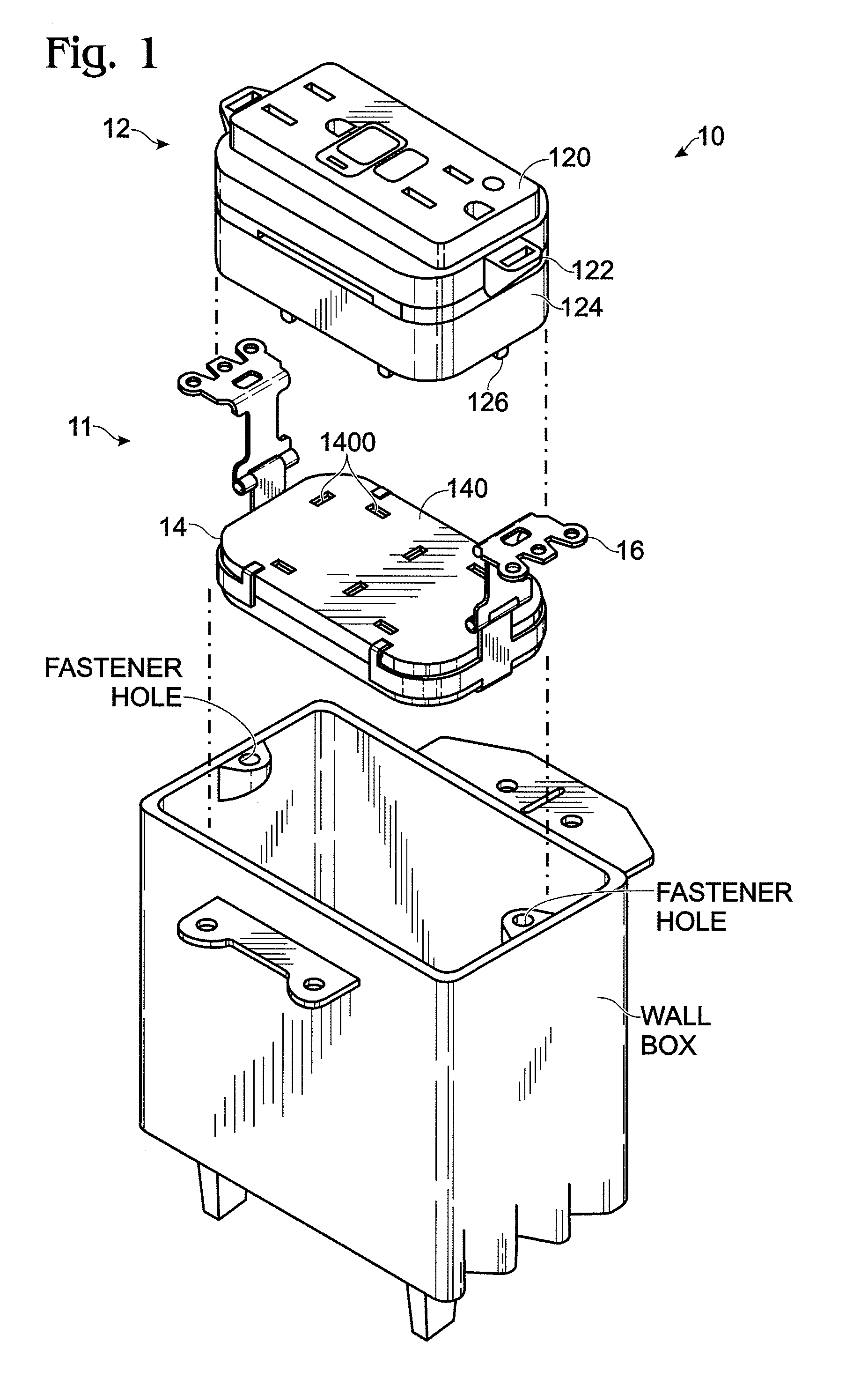
[0024]Reference will now be made in detail to the present exemplary embodiments of the invention, examples of which are illustrated in the accompanying drawings. Wherever possible, the same reference numbers will be used throughout the drawings to refer to the same or like parts. An exemplary embodiment of the modular wiring system of the present invention is shown in FIG. 1, and is designated generally throughout by reference numeral 10.

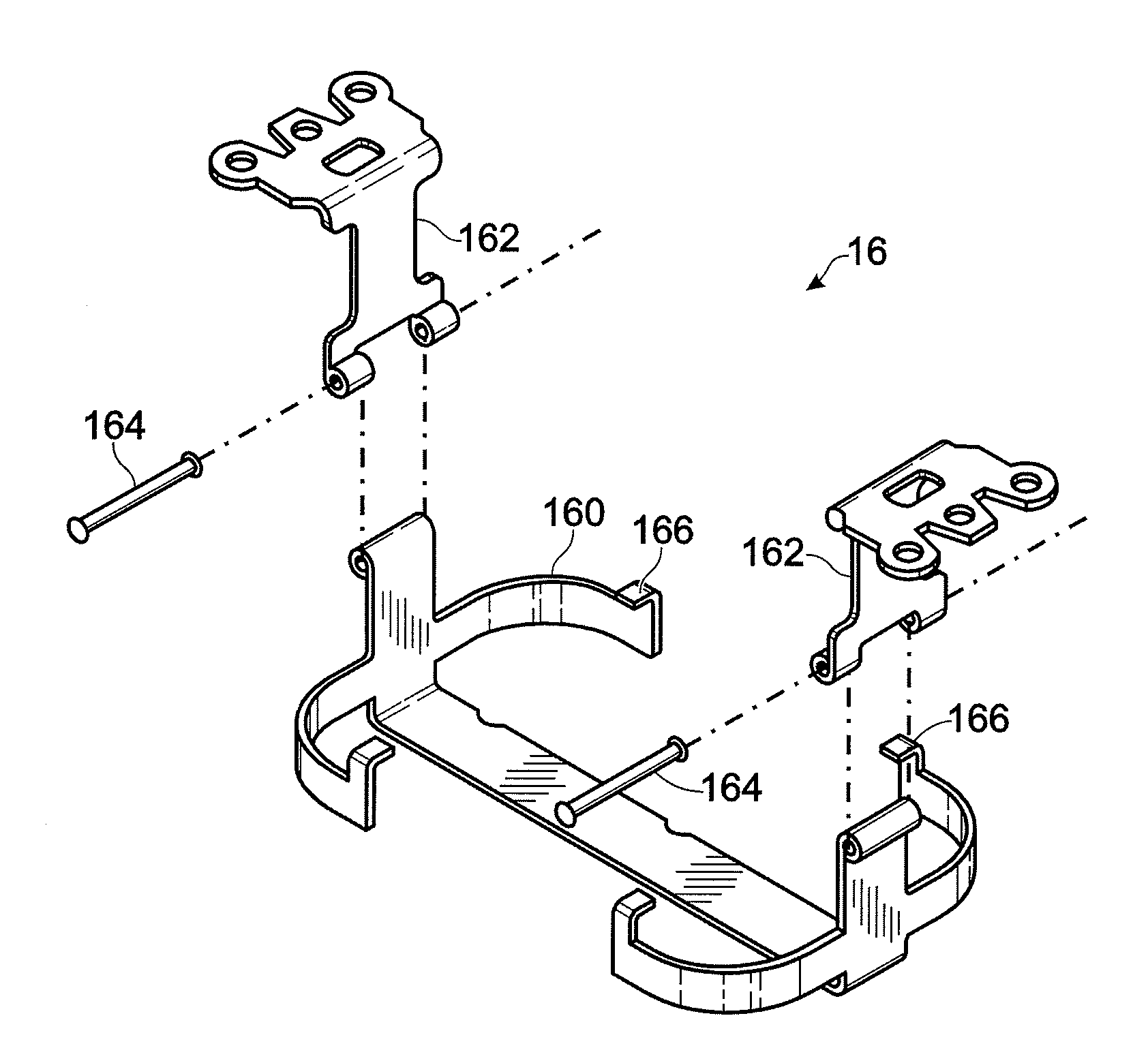
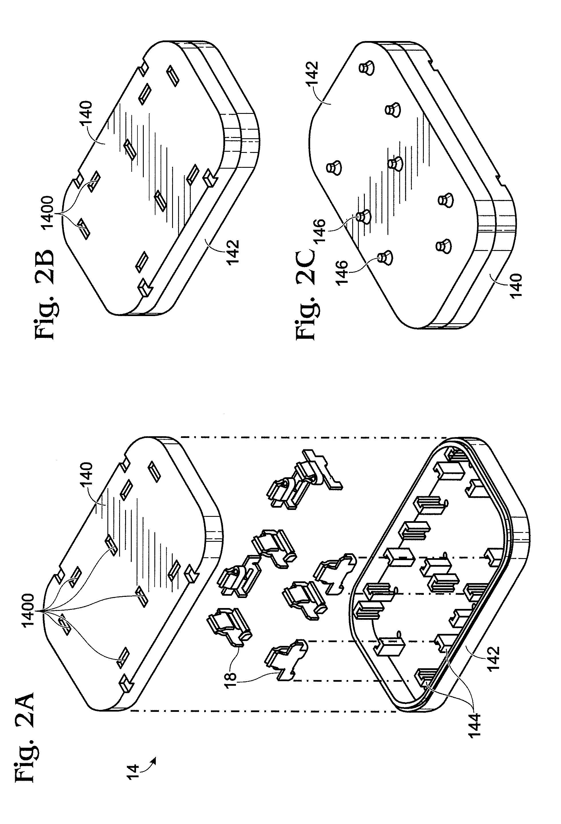
[0025]As embodied herein, and depicted in FIG. 1, an exploded view of the modular system 10 in accordance with one embodiment of the present invention is disclosed. Modular system 10 includes a modular wiring device 12 which is configured to mate with the wall receptacle assembly 11, which is a combination of the wall box receptacle device 14 and adjustable support assembly 16. After the wall receptacle assembly 11 is disposed in the wall box and construction is substantially completed, i.e., the dry-wall is attached to the wall studs, modular wirin...


PUM


Abstract

A modular wiring system including a wall box receptacle device. The system includes a wiring interface disposed on a first side and electrically coupled to a plurality of receptacle openings disposed on a second side. An adjustable support assembly includes a retaining frame configured to secure the wall box receptacle device therein. A first hinged mounting member is rotatably coupled to a first end of the retaining frame, and a second hinged mounting member is rotatably coupled to a second end of the retaining frame. A modular electrical wiring device includes at least one electrical circuit disposed between a cover member and a rear body member. The at least one electrical circuit is coupled to a plurality of male terminal elements accessibly disposed in the rear body member. The plurality of terminal blades are insertable in the plurality of receptacle openings to establish electrical continuity between the plurality of male terminal elements and the wiring interface.

Description

BACKGROUND OF THE INVENTION[0001]1. Field of the Invention[0002]The present invention relates generally to electrical circuit installation, and particularly to electrical devices that facilitate installation of electrical circuits in a building or some other structure.[0003]2. Technical Background[0004]Installing electrical circuits in buildings and / or other structures is typically labor intensive, time-consuming, and a process that requires electricians of various skill levels. As a result the installation process is expensive. The first phase of the installation is commonly referred to as the “rough-in” phase. In new construction, either conduit or armored cable is disposed through out the structure in accordance with the building plans. Junction boxes are installed at appropriate locations, and brackets and metal device boxes are installed throughout the structure where electrical service is desired. Junction boxes, of course, are employed to house the connection point, or juncti...

Claims


Application Information

Patent Timeline
Patent Type & Authority Patents(United States)
IPC IPC(8): H01H9/02
CPCH01R13/447H01R24/76H02G3/086H02G3/123H01H83/04H01R31/06H01R2103/00
Inventor RADOSAVLJEVIC, DEJAN
Owner PASS SEYMOUR
Why Eureka
Try Eureka