Plate conveyor having rapid assembly device

Inactive Publication Date: 2008-02-05
AUMUND FOERDERERBAU
View PDF22 Cites 3 Cited by
  • Summary
  • Abstract
  • Description
  • Claims
  • Application Information

AI Technical Summary

Benefits of technology

[0006]The invention has the advantage that the individual portions of the plate conveyor can be substantially preassembled, and that to join together the terminal link segments of the portions of the plate conveyor that are to be interconnected, merely a single outer closure link member has to be installed in that chain strand of the two-stranded sprocket chain that initially is left incomplete on one side. If on the outwardly projecting terminal outer link member of the terminal link segment of one of the portions of the plate conveyor the as

Problems solved by technology

A problem with such plate conveyors arises during assembly since the plate conveyors must be transported in pre-assembled portions t

Method used


Image

  • Plate conveyor having rapid assembly device
  • Plate conveyor having rapid assembly device
  • Plate conveyor having rapid assembly device

Examples


Embodiment Construction

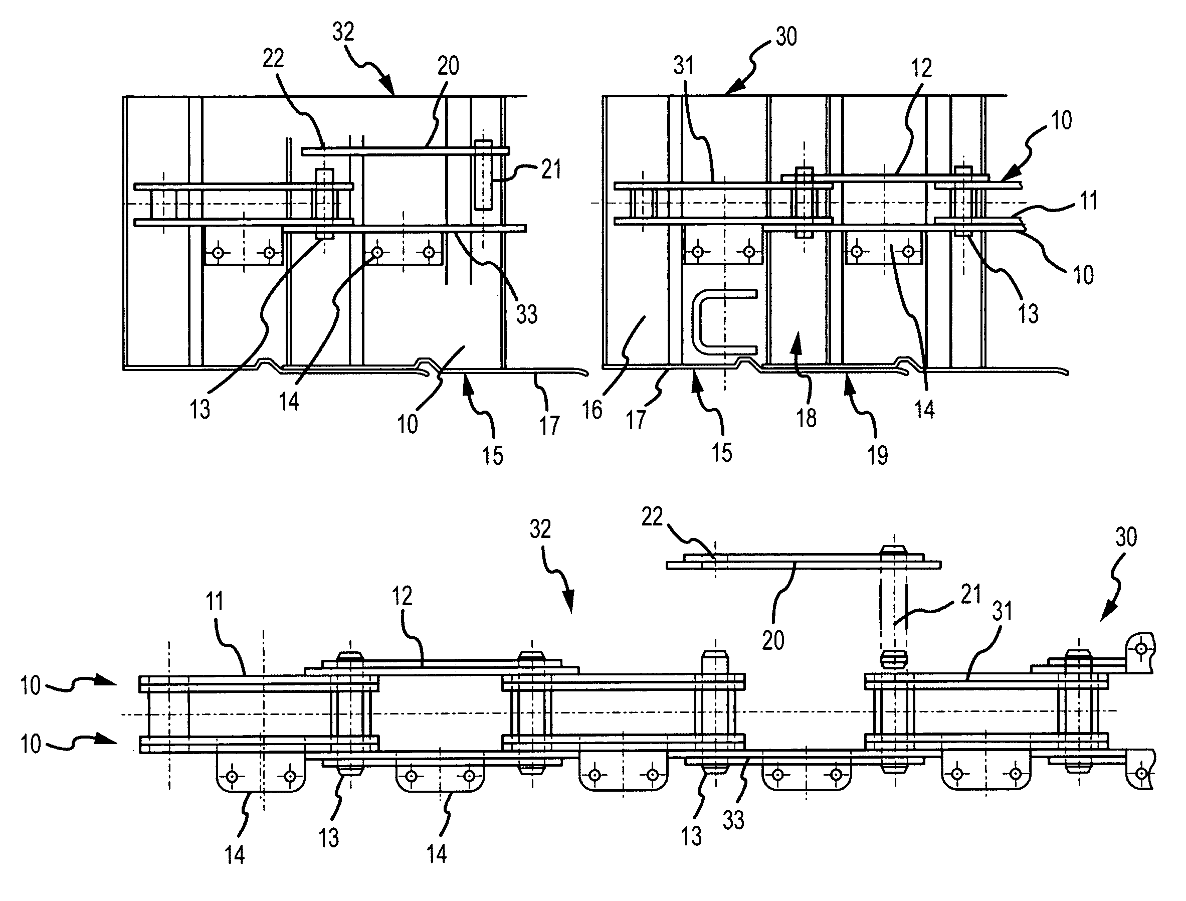
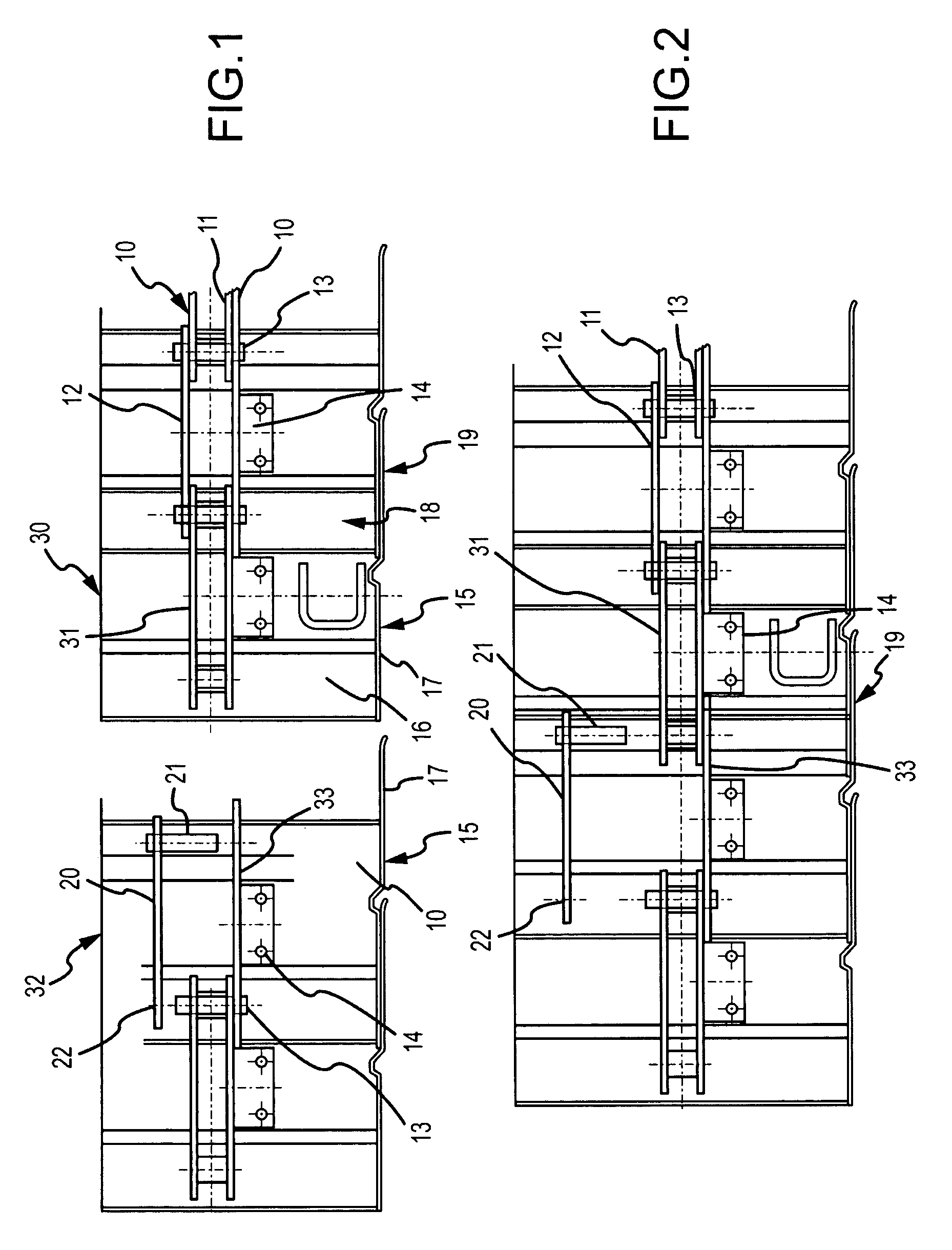
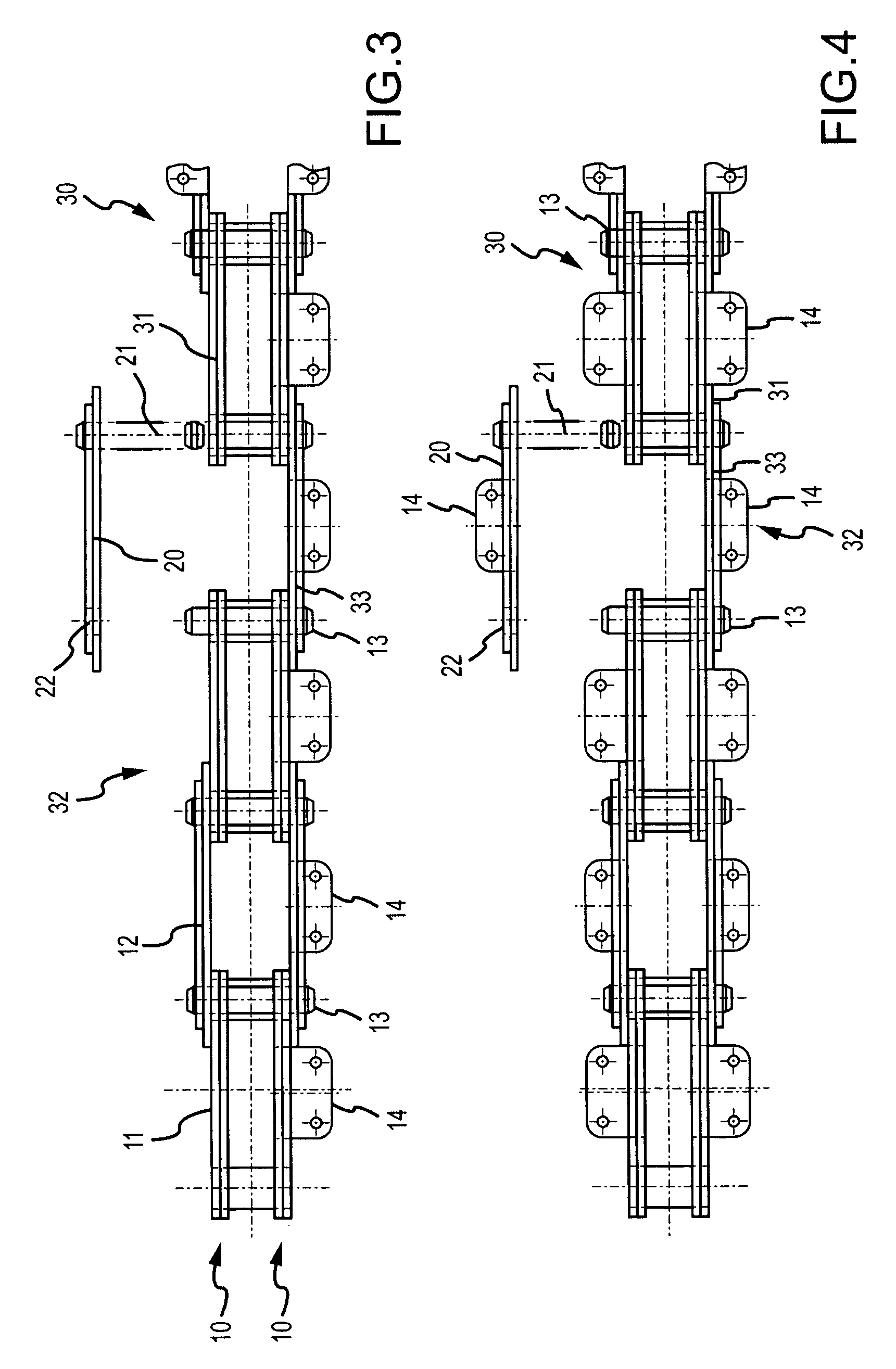
[0014]As can be seen initially from FIG. 1, the sprocket chain, which supports the individual plates 15 of the plate conveyor, comprises two parallel chain strands 10 that extend parallel to one another, whereby each chain strand is comprised of a sequence of inner link members 11 and outer link members 12. The respectively facing inner link members 11 and outer link members 12 are secured to each other by link pins 13 that extend through the link members in common in associated openings, whereby the link pins 13 are deformed with the link members 11, 12 that are set thereon. In the illustrated embodiment, the successively arranged inner link members 11 and outer link members 12 of a given one of the chain strands 10 are provided with brackets 14 to which are secured the plates 15 that form the plate conveyor. The plates 15 have a base 16 and laterally and vertically raised side edges 17, whereby the bases 16 and the side edges 17 of the individual plates 15 respectively overlap one...


PUM


Abstract

A plate conveyor having overlapping plates and a plate-supporting sprocket chain composed of two parallel chain strands formed of inner link members and outer link members, facing ones of which are connected by link pins. The chain is in the form of at least two preassembled portions that are to be interconnected by terminal link segments. A first terminal link segment is comprised of two parallel, outwardly projecting terminal inner link members, with a plate connected to at least one of them. A second terminal link segment is formed by a terminal outer link member, one end of which is connected to a link pin. The terminal outer link member projects outwardly on one side of the second terminal link segment and is connected to a plate. An outer closure link member is disposed across from the terminal outer link member and has an end adapted to be placed on the link pin. Another end of the outer closure link member has a further link pin adapted to extend through both of the terminal inner link members as well as through the other end of the terminal outer link member.

Description

[0001]This specification for the instant application should be granted the priority date of Nov. 19, 2002, the filing date of the corresponding German patent application 102 54 049.7 as well as the priority date of 18 Nov. 2003, the filing date of the corresponding International patent application PCT / EP2003 / 012892.BACKGROUND OF THE INVENTION[0002]The present invention relates to a plate conveyor having identical plates that are supported by a sprocket chain and that in the conveying direction of the plate conveyor have their bases, as well as vertically extending side edges thereof, reciprocally overlap, whereby the sprocket chain is composed of two chain strands that are disposed parallel to one another and are each formed by a sequence of inner link members and outer link members, wherein facing ones of the inner link members and outer link members are connected by respective common link pins that extend through associated openings of the link members, and wherein the plates of t...

Claims


Application Information

Patent Timeline
IPC IPC(8): B65G29/00B65G17/06B65G17/38B65G17/44
CPCB65G17/067B65G17/38B65G17/44B65G17/06B65G17/08
Inventor DUFHAUS, KARL-JOSEF
Owner AUMUND FOERDERERBAU
Why Eureka
Try Eureka