Splice module with optical fiber aligning passageway determining inscribed circle of reduced radius

Inactive Publication Date: 2005-02-22
JAPAN AVIATION ELECTRONICS IND LTD
View PDF10 Cites 0 Cited by
  • Summary
  • Abstract
  • Description
  • Claims
  • Application Information

AI Technical Summary

Benefits of technology

It is an object of the present invention to provide a splice module which can achieve a prec

Problems solved by technology

However, there is no consideration as to a suitable relation between passage ways and optical fibers.
For example, the splice module according to JP-A 2002-48934 cannot achieve a precise alignment of optical fibers because the sectional area of each passage way is

Method used


Image

  • Splice module with optical fiber aligning passageway determining inscribed circle of reduced radius
  • Splice module with optical fiber aligning passageway determining inscribed circle of reduced radius
  • Splice module with optical fiber aligning passageway determining inscribed circle of reduced radius

Examples


Embodiment Construction

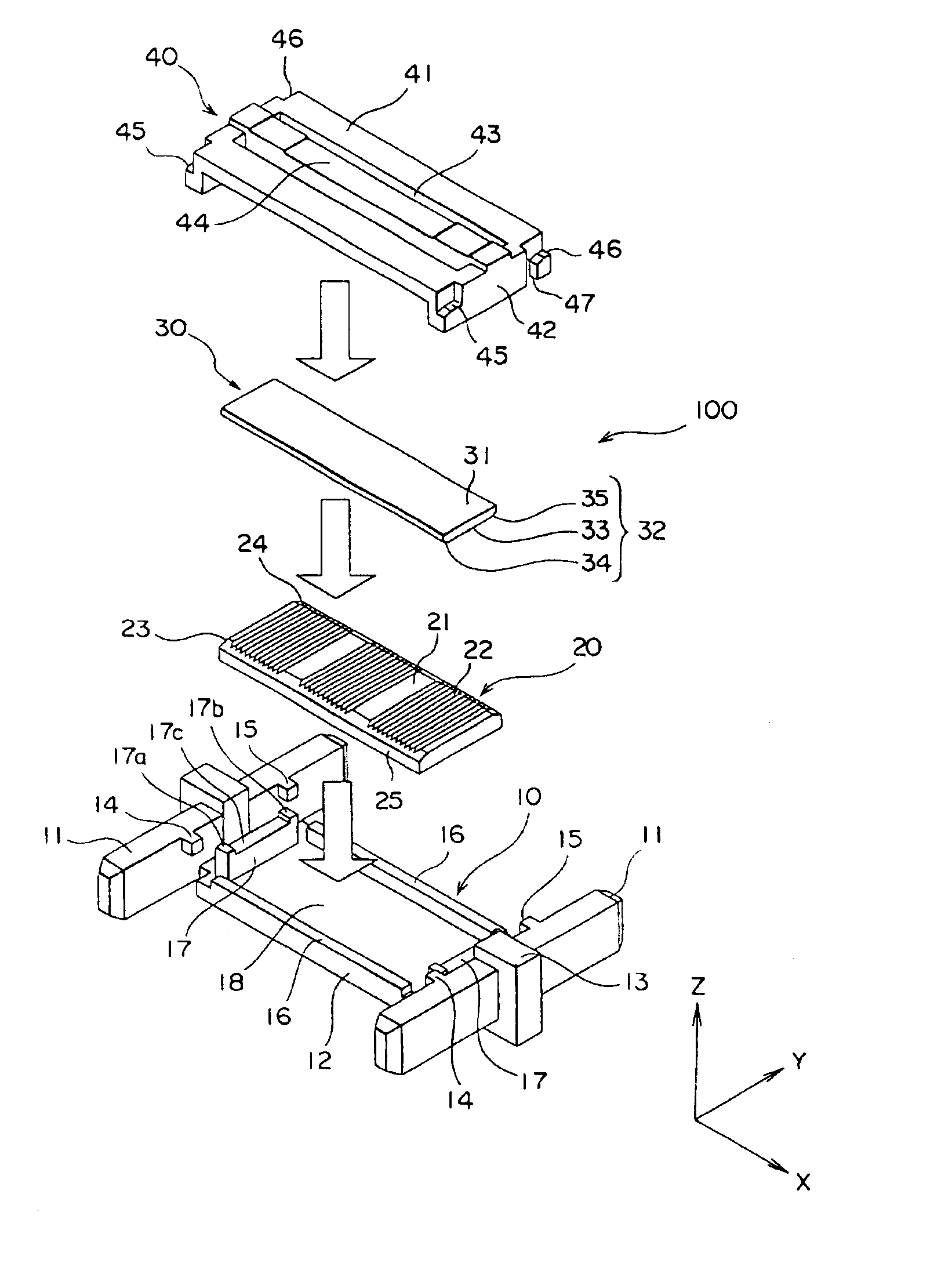
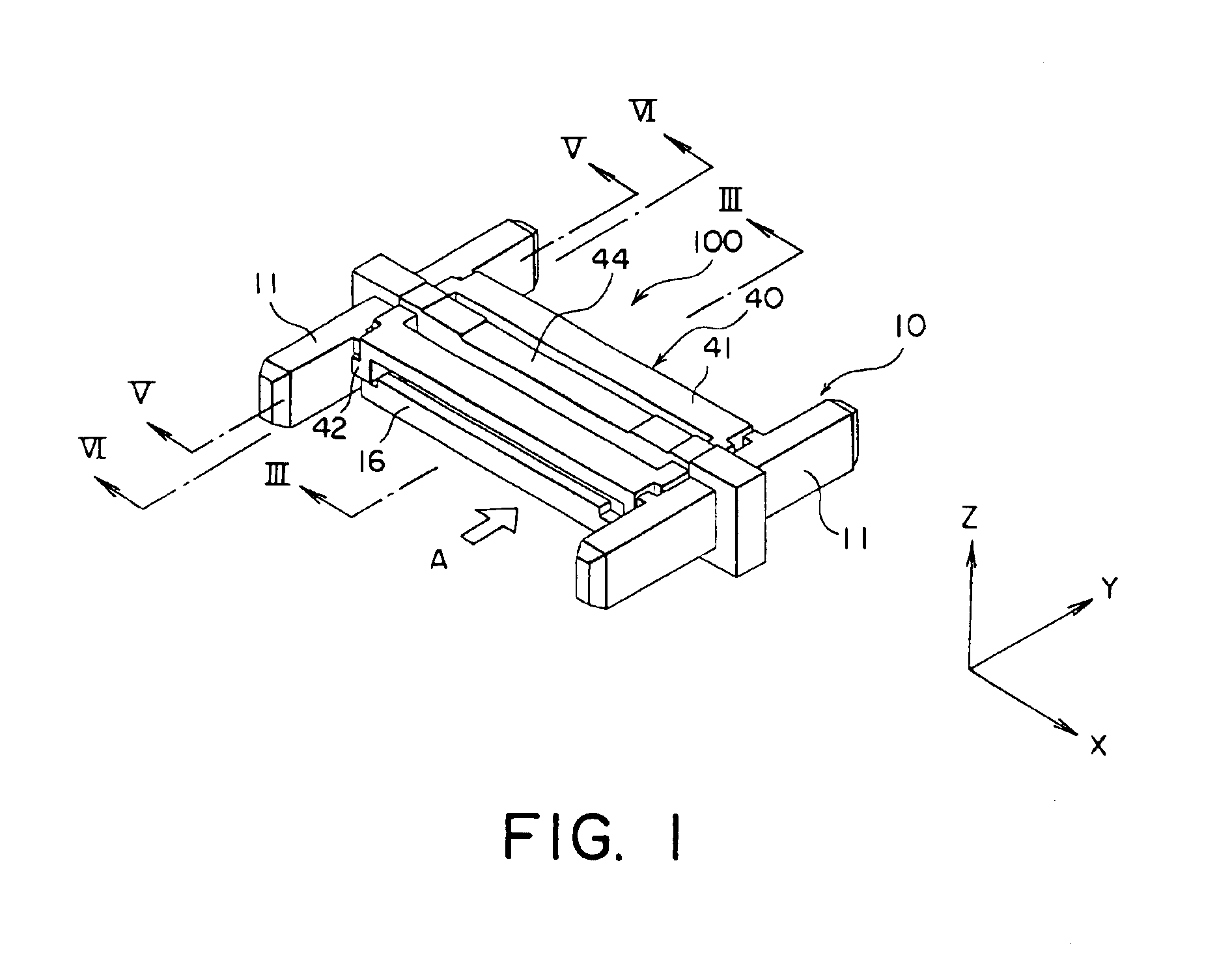
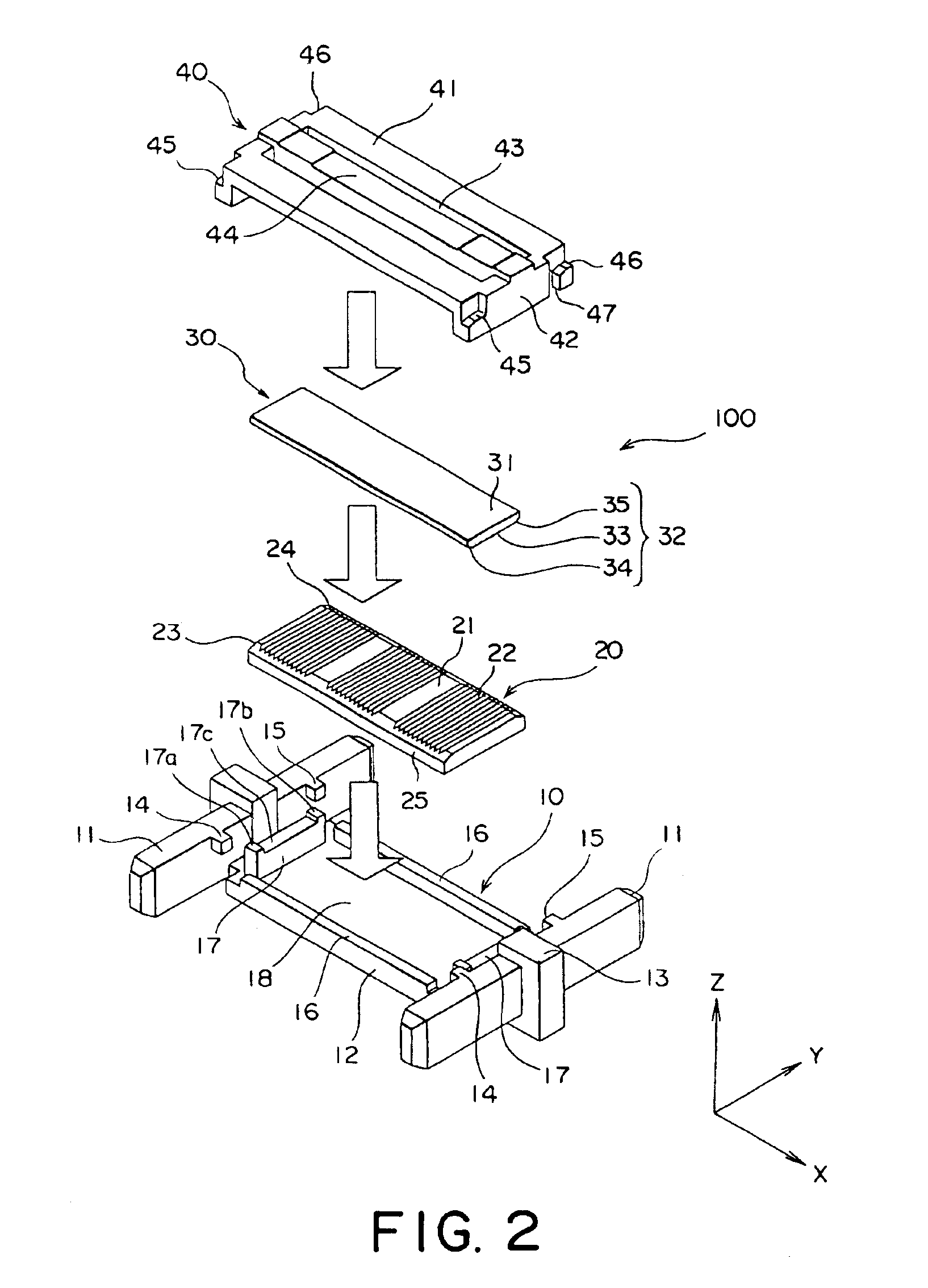
With reference to FIGS. 1 and 2, a mechanical splice module 100 for optical fibers in accordance with an embodiment of the present invention comprises a main member 10, first and second plates 20, 30 and a pressing lid 40.

As shown in FIG. 2, the main member 10 comprises a pair of frame portions 11 and a base portion 12. Each of the frame portions 11 extends in a Y-direction and is arranged apart from the other frame portion 11 in an X-direction perpendicular to the Y-direction. The base portion 12 is positioned between the frame portions 11 in the X-direction and connects therebetween.

With reference to FIGS. 2 to 5, each of the frame portions 11 is provided with a stopper portion 13, which is positioned at the middle of the frame portion 11 in the Y-direction and has a cross section larger than the frame portion in a plane perpendicular to the Y-direction. As described in JP-A 2002-48934, the splice module 100 of the type is used together with a pair of plug connectors, each of whic...


PUM


Abstract

A splice module for optically interconnecting ends of first and second optical fibers (200, 300), each of which has a predetermined radius (Rf). The splice module comprises first and second plates (20, 30), both of which are made of silicon. The first plate 20 is provided with grooves (22). The second plate (30) is arranged on the first plate (20) to cover the grooves (22) and to define passage ways (26) for receiving and aligning the ends of the first and the second optical fibers (200, 300). The passage way (26) has an inscribed circle (28), which has a radius (Ri) larger than the predetermined radius (Rf) by a predetermined difference (D) between 0.5 μm and 1.0 μm, both inclusive.

Description

This application claims priority to prior Japanese application JP 2002-283571, the disclosure of which is incorporated herein by reference.BACKGROUND OF THE INVENTIONThis invention relates to a splice module for use in optical fiber alignment.JP-A 2002-48934 discloses a splice module for use in optical fiber alignment. In the splice module, there are a substrate and a presser plate, wherein the substrate is formed with a plurality of grooves, each of which extends in a predetermined direction. The presser plate is arranged on the substrate to define a plurality of passage ways, each of which is for receiving and aligning the ends of optical fibers. In particular, the presser plate is formed with a plurality of guide portions, which are positioned in accordance with the respective grooves to substantially enlarge the opposite ends of each groove. The splice module can provide an insertion ease.JP-A 2001-201668 discloses another splice module for optical fibers. The splice module has ...

Claims


Application Information

Patent Timeline
IPC IPC(8): G02B6/36G02B6/38G02B6/24G02B6/40
CPCG02B6/3636G02B6/3806G02B6/3692G02B6/3652G02B6/40
Inventor TAKEDA, JUNKOREEDA, YUICHI
Owner JAPAN AVIATION ELECTRONICS IND LTD
Why Eureka
Try Eureka