Damper device

Active Publication Date: 2020-08-20
AISIN CORP +1
View PDF0 Cites 0 Cited by
  • Summary
  • Abstract
  • Description
  • Claims
  • Application Information

AI Technical Summary

Benefits of technology

[0008]In the above damper device, the ring gear of the rotary inertia mass damper includes the following: the annulus gear having the internal teeth that mesh with the pinion gears; and a weight body that is fixed to the annulus gear such that the weight body is in contact with one side surface of the annulus gear. The inner circumferential surface of the weight body is supported in the radial direction by the tip of the pinion gear or the outer circumferential surface of the washer located on a side of the pinion gear. In this way, an external gear having a simple structure can be adopted as the pinion gear and it is possible to suppress an increase in cost that results from an increase in the number of assembly parts of the pinion gear and from an increase in the number of steps of the manufacturing and assembly process. Since the inner ci

Problems solved by technology

However, with the damper device described above, there is a possibility that costs will be increased due to an increase in the number of assembly parts of the pinion gear and an increase in the number of steps of the manufacturing and

Method used


Image

  • Damper device
  • Damper device
  • Damper device

Examples


Embodiment Construction

[0022]Next, an embodiment of the present disclosure is described with reference to the drawings.

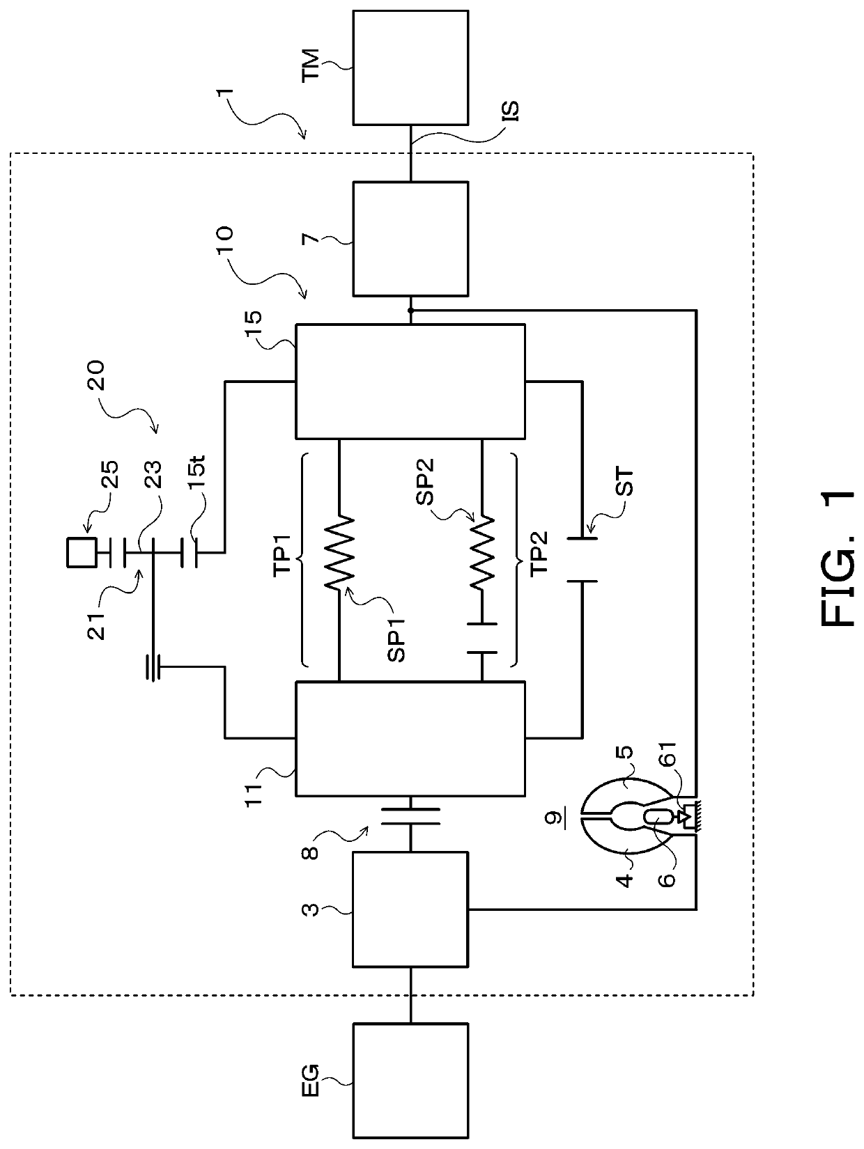
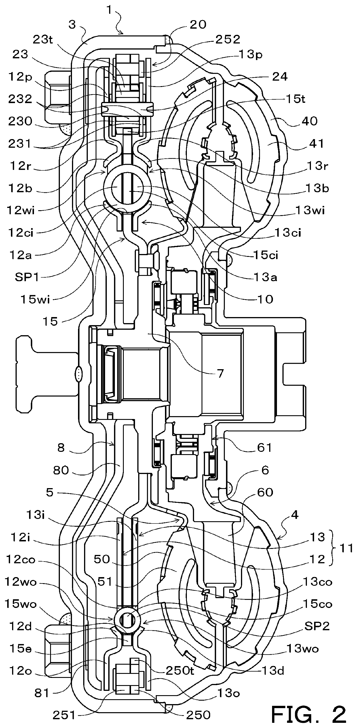
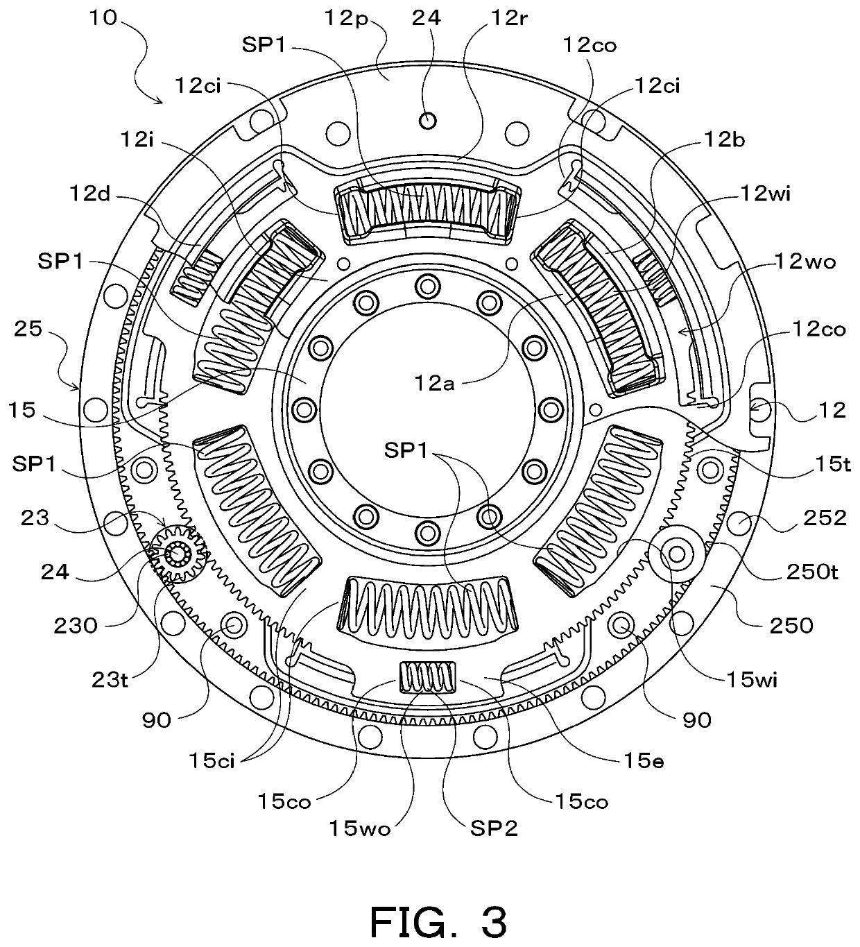
[0023]FIG. 1 is a schematic diagram of a starting apparatus 1 including a damper device 10 according to the present disclosure, and FIG. 2 is a cross-sectional view of the starting apparatus 1. The starting apparatus 1 illustrated in these drawings is adapted to be mounted on a vehicle having an engine (an internal combustion engine) EG as a drive unit. In addition to the damper device 10, the starting apparatus 1 includes the following: a front cover 3 as an input member coupled to a crankshaft of the engine EG to receive torque transmitted from the engine EG; a pump impeller (an input-side fluid transmission element) 4 fixed to the front cover 3; a turbine runner (an output-side fluid transmission element) 5 rotatable coaxially with the pump impeller 4; a damper hub 7 as an output member coupled to the damper device 10 and fixed to an input shaft IS of a transmission TM that is an autom...


PUM


Abstract

A damper device including an input element and an output element; an elastic body transmitting torque between the input element and the output element; and a rotary inertia mass damper having a mass body. The rotary inertia mass damper includes a sun gear, a carrier rotatably supporting pinion gears, and a ring gear that meshes with the pinion gears and serving as the mass body. A pair of washers is located on both sides of each pinion gear axially. The ring gear includes an annulus gear having internal teeth meshing with the pinion gears and a weight body fixed to the annulus gear such that the weight body is in contact with a side surface of the annulus gear. An inner circumferential surface of the weight body is supported in a radial direction by a tip of the pinion gear or an outer circumferential surface of the washer.

Description

CROSS REFERENCE TO RELATED APPLICATIONS[0001]This application is a National Stage of International Application No. PCT / JP2018 / 042194, filed Nov. 14, 2018, claiming priority to Japanese Patent Application No. 2017-219521, filed Nov. 14, 2017, the contents of which are incorporated in their entirety.TECHNICAL FIELD[0002]The present disclosure relates to a damper device including an elastic body that transmits torque between an input element and an output element, and a rotary inertia mass damper.BACKGROUND ART[0003]Hitherto, as a rotary inertia mass damper of a damper device of this type, a rotary inertia mass damper having a planetary gear including a sun gear that rotates as a unit with an output element, a carrier that supports a plurality of pinion gears so that the pinion gears are rotatable and that rotates as a unit with an input element, and a ring gear that meshes with the pinion gears and that functions as a mass body is known (for example, see Patent Document 1). The pinion...

Claims


Application Information

Patent Timeline
IPC IPC(8): F16F15/134F16H45/02F16F15/14F16D3/12
CPCF16F15/1478F16H2045/0268F16D3/12F16H2045/0226F16H45/02F16F15/13469F16H1/28F16F15/13484F16H2045/0263
Inventor YOSHIKAWA, TAKUYAKINOSHITA, TOMONORITANIGUCHI, TETSUROKATO, AKIYOSHIOI, YOICHI
Owner AISIN CORP
Why Eureka
Try Eureka