Color liquid crystal display panel

Inactive Publication Date: 2006-03-28
SHARP KK
View PDF2 Cites 9 Cited by
  • Summary
  • Abstract
  • Description
  • Claims
  • Application Information

AI Technical Summary

Benefits of technology

[0013]It is therefore an object of the present invention to provide a color liquid crystal display panel capable of operating both in a reflection mode and in a transmission mode and displaying images with a desirable saturation both in

Problems solved by technology

Therefore, the saturation of the reflected light will be low for the performance

Method used


Image

  • Color liquid crystal display panel
  • Color liquid crystal display panel
  • Color liquid crystal display panel

Examples


embodiment 1

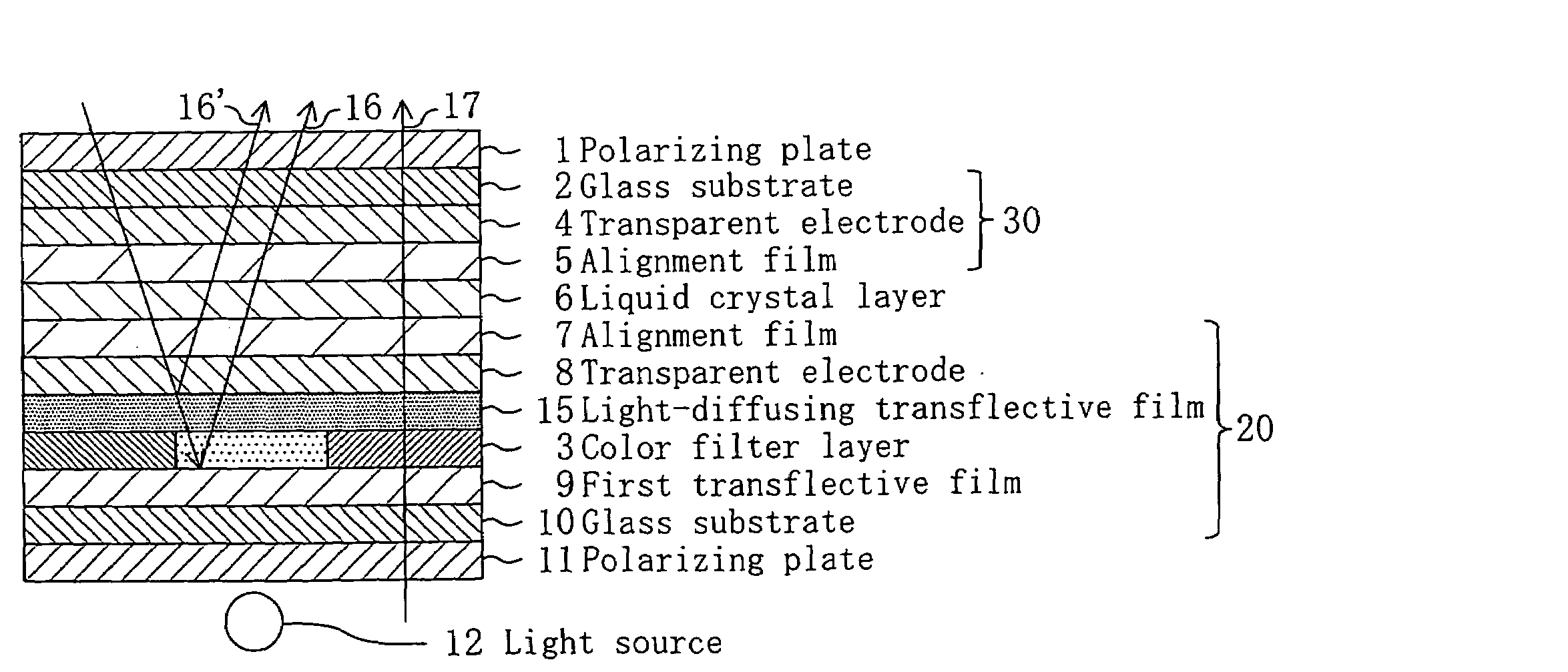
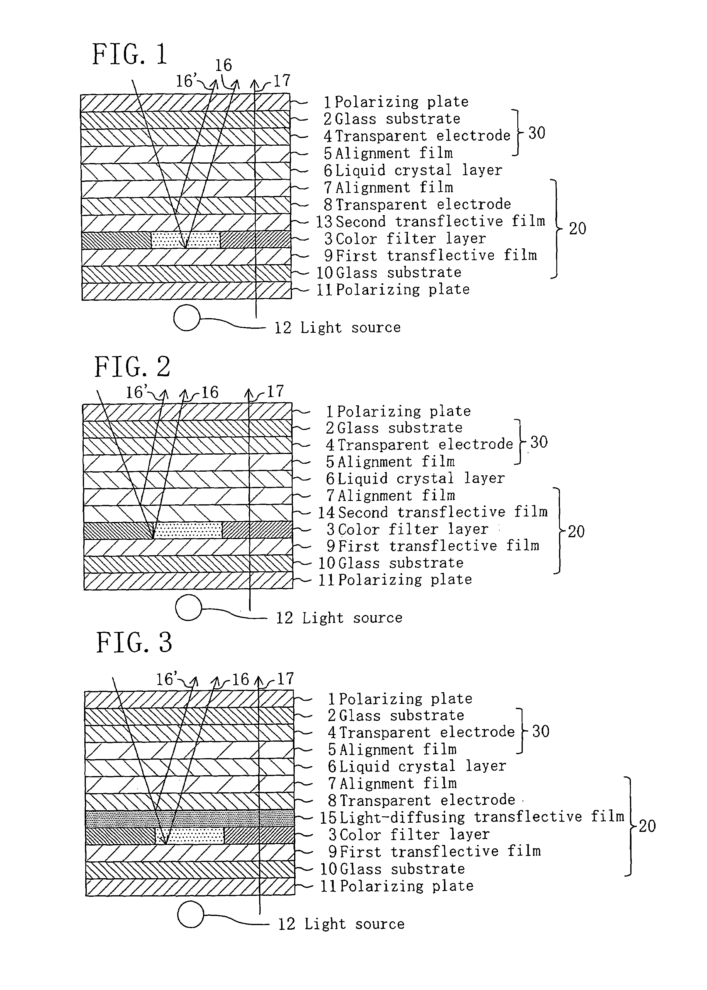
[0031]FIG. 1 is a cross-sectional view schematically illustrating a liquid crystal display device of Embodiment 1. The liquid crystal display device of the present embodiment includes a liquid crystal display panel, a light source 12, and a pair of polarizing plates 1 and 11 provided on opposite sides of the liquid crystal display panel. The liquid crystal display panel includes a light-source-side substrate (color filter substrate) 20 provided closer to the light source 12, a viewer-side substrate (counter substrate) 30 provided on the viewer side so as to oppose the light-source-side substrate 20, and a liquid crystal layer 6 between the substrate 20 and 30.

[0032]The light-source-side substrate 20 includes a first transflective film 9, a color filter layer 3, a second transflective film 13, a transparent electrode 8 and an alignment film 7 layered in this order on a glass substrate 10. The viewer-side substrate 30 includes a transparent electrode 4 and an alignment film 5 layered ...

embodiment 2

[0045]FIG. 2 is a cross-sectional view schematically illustrating a liquid crystal display device of Embodiment 2. In this and subsequent figures, elements having substantially the same functions as those of the liquid crystal display device of Embodiment 1 will be denoted by the same reference numerals, and will not be further described below.

[0046]The liquid crystal display device of the present embodiment does not include the transparent electrode 8 used in Embodiment 1, but a second transflective film 14 functions as an electrode for driving the liquid crystal molecules in the liquid crystal layer 6. In other words, the second transflective film 14 is an electrode with a transflective function. The second transflective film 14 is formed from a conductive film such as a metal film, and the thickness thereof is adjusted so as to be transflective.

[0047]According to the present embodiment, an electrode is formed in the formation of the second transflective film, whereby it is not ne...

embodiment 3

[0048]FIG. 3 is a cross-sectional view schematically illustrating a liquid crystal display device of Embodiment 3. In the liquid crystal display device of the present embodiment, the second transflective film is a light-diffusing transflective film 15 that is not only transflective but is also light diffusing.

[0049]The light-diffusing transflective film 15 is, for example, a layered structure of a transparent resin film having surface irregularities and a transflective film formed on the transparent resin film. Specifically, an acrylic resin film is formed and subjected to a heat treatment, whereby the surface thereof is deformed into surface irregularities. A transflective film is formed by a sputtering method, or the like, on the irregular surface to obtain a light-diffusing transflective film. The reflectance thereof can be controlled by adjusting the thickness of the transflective film.

[0050]According to the present embodiment, in a case where the first transflective film 9 has ...


PUM


Abstract

A color liquid crystal display panel includes: a first substrate provided on a light source side; a second substrate provided on a viewer side so as to oppose the first substrate; a liquid crystal layer provided between the first substrate and the second substrate; a color filter layer provided between the first substrate and the second substrate; a first transflective film provided closer to the light source than the liquid crystal layer and the color filter layer for reflecting ambient light coming from the viewer side while transmitting therethrough light-source light coming from the light source side; and a second transflective film provided closer to the viewer than the color filter layer for reflecting the ambient light while transmitting therethrough the light-source light.

Description

BACKGROUND OF THE INVENTION[0001]1. Field of the Invention[0002]The present invention relates to a color liquid crystal display panel that operates in a reflection mode and in a transmission mode.[0003]2. Description of the Background Art[0004]FIG. 4 and FIG. 5 are cross-sectional views schematically illustrating semi-transmissive color liquid crystal display devices of Conventional Examples 1 and 2, respectively, each of which operates in a reflection mode and in a transmission mode.[0005]The process of manufacturing a liquid crystal display device of FIG. 4 will now be described. A color filter layer 3 is formed on a viewer-side glass substrate 2 and subjected to an overcoat process using a spin coating method, after which a sputtered transparent electrode 4 is patterned. An alignment film 5 is formed thereon using a roll coater method and subjected to a rubbing treatment.[0006]An SiO2 film and a thin aluminum film are sputtered on a light-source-side glass substrate 10, and a tra...

Claims


Application Information

Patent Timeline
IPC IPC(8): G02F1/1333G02B5/20G02B5/30G02F1/1335
CPCG02F1/133555G02F1/133536G02F1/133514G02F2201/17
Inventor ASHIDA, TAKEYUKINOMURA, KIMITAKA
Owner SHARP KK
Why Eureka
Try Eureka