Mechanism for self-alignment of communications elements in a modular electronic system

Inactive Publication Date: 2006-05-18
IBM CORP
View PDF4 Cites 0 Cited by
  • Summary
  • Abstract
  • Description
  • Claims
  • Application Information

AI Technical Summary

Benefits of technology

[0010] The alignment frame is installed in a side of a brick through a cutout in a side or wall of the brick. The cutout is slightly larger than the alignment frame, allowing the alignment frame to shift within the cutout to allow alignment with the adjacent alignment frame. The present mechanism further comprises a set of springs to push the alignment frame

Problems solved by technology

The rack/chassis-based architecture suffers from several operational disadvantages: scaling difficulty; cable management; connector unreliability; and unreliability of wire and cable assemblies.
These disadvantages contribute to the overall unreliability of today's high-performance computer and communications syst

Method used


Image

  • Mechanism for self-alignment of communications elements in a modular electronic system
  • Mechanism for self-alignment of communications elements in a modular electronic system
  • Mechanism for self-alignment of communications elements in a modular electronic system

Examples


Embodiment Construction

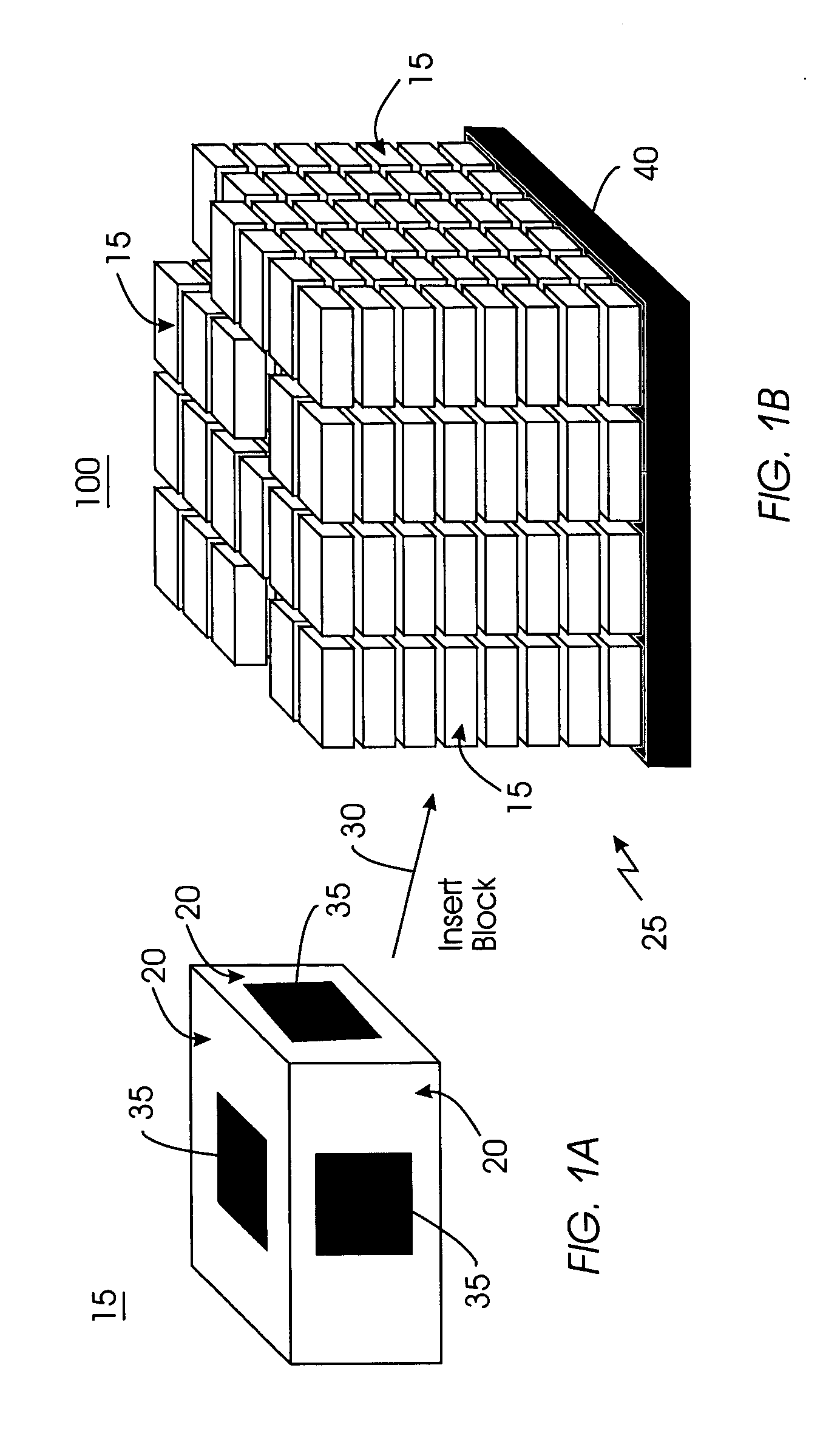
[0020]FIG. 1 (FIGS. 1A, 1B) portrays an exemplary modular electronic system 100 in which a mechanism for self-alignment of communications elements can be used. The modular electronic system 100 comprises a plurality of generally identical or similar bricks 15 that are collectively referred to as subsystem 25. The bricks 15 are stacked together to form the modular electronic system 100. In this example, each brick 15 has a plurality of contact surfaces 20 that are adapted to be located in close proximity to, or in contact with the contact surfaces of other bricks 15. Arrow 30 illustrates the placement of a brick 15 within the modular electronic system 100.

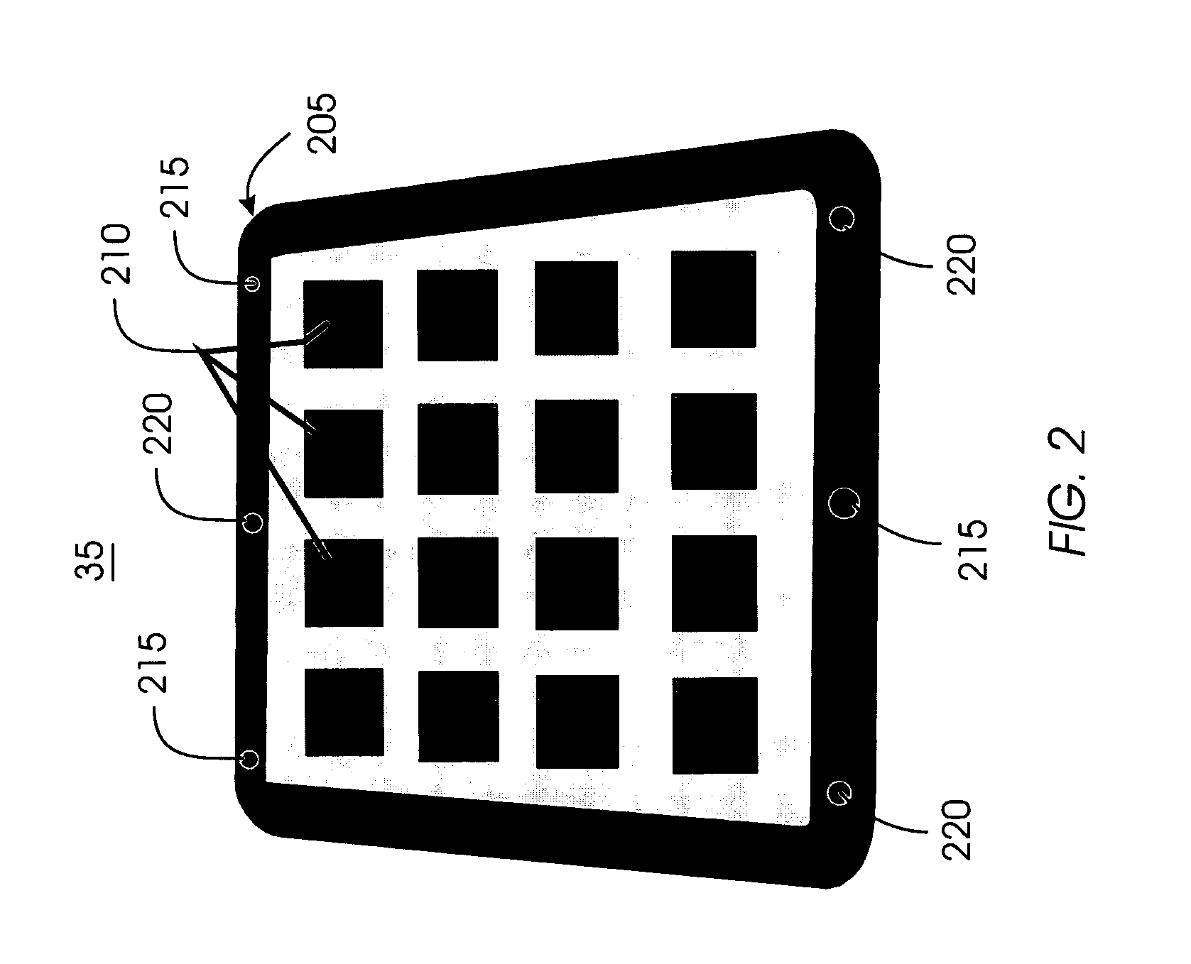
[0021] In this example, each contact surface 20 accommodates a communications element 35. In turn, the communications element 35 may comprise one or more capacitive half-couplers, a transmitter, a receiver, or a transceiver. Each brick 15 comprises a data processing unit (server), a data storage unit, a networking unit, or another ...


PUM


Abstract

A mechanism that automatically achieves alignment of the communications elements during assembly of a modular computer system, without the need for human intervention. The mechanism comprises an alignment frame provided with bumps and depressions. The bumps in the alignment frames mate with the depressions on adjacent alignment frames. Each depression comprises an entrance opening that is wider than the diameter of the bumps. The diameter of the entrance opening is determined by the expected accuracy of the alignment of subsystems or bricks within the modular electronic system. When it is desired to align the communication elements, the alignment frames are brought into engagement by causing alignment guides to slide past each other, and to guide the bumps in the alignment frames into the depressions in the adjacent alignment frames. The mechanism further comprises a set of springs that force the allow the alignment frames to be retained securely by the communications elements.

Description

FIELD OF THE INVENTION [0001] The present invention generally relates to computer systems, and more particularly to a scalable computer comprising communications elements each having capacitive couplers or other wireless communication devices mounted on subsystem surfaces for communication with adjacent subsystems. More specifically, the present invention pertains to a mechanism for automatically achieving self-alignment between subsystems or communications elements with sufficient accuracy. BACKGROUND OF THE INVENTION [0002] Contemporary computer and communications systems commonly comprise several subsystems, each implementing one or more computation or communication functions. Examples include computer servers, Internet web servers, storage servers, and packet-based communications switches. Each subsystem comprises its unique electrical and mechanical elements, including printed-circuit wiring board assemblies, internal wiring and connectors, etc. Each subsystem is outfitted with...

Claims


Application Information

Patent Timeline
IPC IPC(8): H05K5/00
CPCG06F1/181H04Q2201/02H04Q1/035H04Q1/023H04Q1/03
Inventor GARNER, ROBERT BARTONWILCKE, WINFRIED WOLFGANGWILLIAMS, RICHARD MICHAEL
Owner IBM CORP
Why Eureka
Try Eureka