Eureka AIR delivers breakthrough ideas for toughest innovation challenges, trusted by R&D personnel around the world.

Deck for magnetic recording/reproducing apparatus

a recording/recording apparatus and magnetic technology, applied in the field of decks for magnetic recording/recording apparatuses, can solve the problems of increased manufacturing cost, increased manufacturing cost, increased manufacturing cost, etc., and achieve the effect of reducing the size of the deck, reducing the number of connecting parts, and low pri

Inactive Publication Date: 2008-02-05
SAMSUNG ELECTRONICS CO LTD
View PDF8 Cites 6 Cited by
  • Summary
  • Abstract
  • Description
  • Claims
  • Application Information

AI Technical Summary

Benefits of technology

[0017]An object of the present invention is to provide a deck for a magnetic recording / reproducing apparatus, in which a single chassis structure is employed, thereby minimizing the size of the deck, and in which all of the switches and sensors for operating the deck are disposed in a single circuit board, thereby reducing the connecting portions for connecting the components with the main circuit board.
[0018]Another object of the present invention is to provide a deck for a magnetic recording / reproducing apparatus, in which a low-priced typical PCB is employed, thereby significantly reducing the manufacturing cost of the device.

Problems solved by technology

The FPCB is formed of a flexible plastic sheet on which a precise circuit is printed, and more expensive than a typical Printed Circuit Board (PCB).
Therefore, there is a problem that the manufacturing cost is increased since a great quantity of high-priced FPCB is used in the deck and chassis of the conventional magnetic recording / reproducing apparatus.
Particularly, since the deck can not use the typical PCB instead of the high-priced FPCB due to its size, the manufacturing cost is increased.
If the number of connecting portions is increased, as described above, the number of assembling processes is increased, and the degree of design freedom in the main circuit is restricted.

Method used


Image

  • Deck for magnetic recording/reproducing apparatus
  • Deck for magnetic recording/reproducing apparatus
  • Deck for magnetic recording/reproducing apparatus

Examples


Embodiment Construction

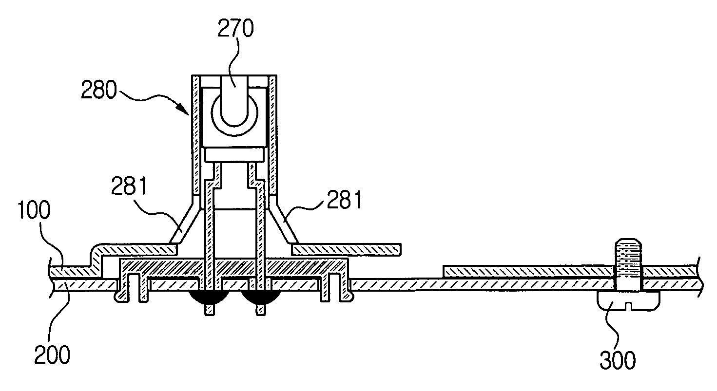
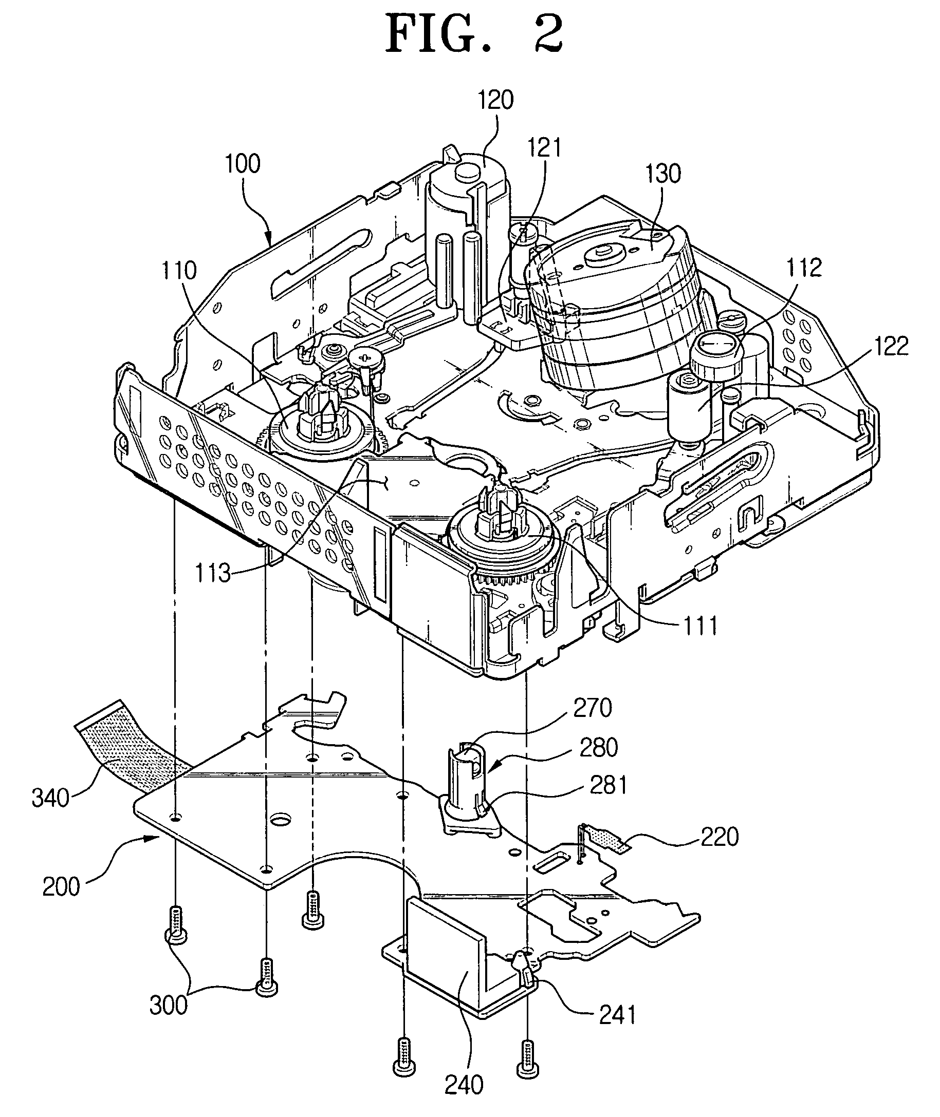
[0034]Reference will now be made in detail to the preferred embodiments of the present invention, examples of which are illustrated in the accompanying drawings.

[0035]FIGS. 2 and 4 schematically show a deck for magnetic recording / reproducing apparatus according to an embodiment of the present invention. A reference numeral 100 designates a chassis, 200 is a switch / sensor circuit board.

[0036]In the chassis 100, a plurality of structures are formed, constituting a mechanical mechanism for loading a tape and a recording / reproducing information. In the switch / sensor circuit board, a plurality of switches and sensors are formed, constituting an electronic mechanism for detecting an operational state of the deck and the structures. The deck for a magnetic recording / reproducing apparatus of the present embodiment further comprises a cassette housing (not shown) in which a cassette tape is disposed.

[0037]The plurality of structures constituting the mechanical mechanism comprises a reel asse...


PUM

PropertyMeasurementUnit
Flexibleaaaaaaaaaa
flexibleaaaaaaaaaa
sizeaaaaaaaaaa

Abstract

Disclosed is a deck for a magnetic recording / reproducing apparatus. The deck has a chassis in which a plurality of structures constituting a mechanical mechanism for loading a tape and recording or reproducing information; and a switch / sensor circuit board in which a plurality of switches and sensors constituting an electronic mechanism for detecting an operation of the deck and a state of the structures. The switch / sensor circuit board is formed of a PCB and assembled to a lower surface of the chassis.

Description

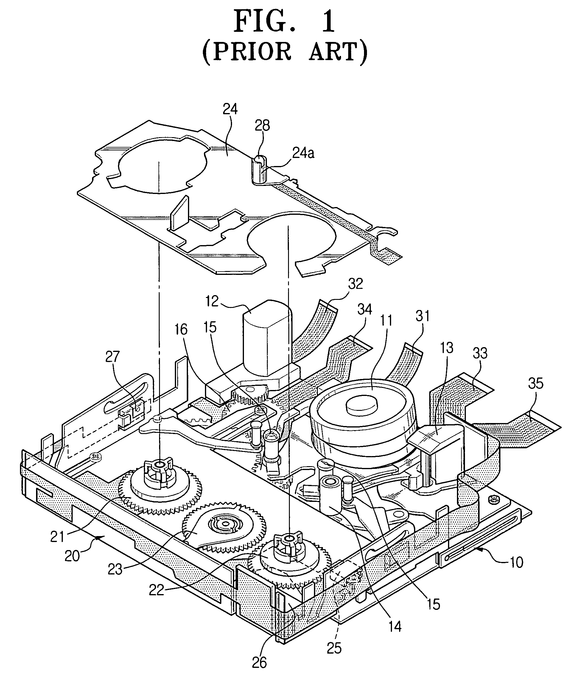
CROSS-REFERENCE TO RELATED APPLICATIONS[0001]This application claims the benefit under 35 U.S.C. §119(a) of Korean Patent Application No. 2004-45305, filed on Jun. 18, 2004, the entire contents of which is incorporated herein by reference.BACKGROUND OF THE INVENTION[0002]1. Field of the Invention[0003]The present invention relates to a deck for a magnetic recording / reproducing apparatus.[0004]2. Description of the Related Art[0005]Generally, a magnetic recording / reproducing apparatus, such as a Video Cassette tape Recorder (VCR) and a Digital Versatile Camcorder (DVC)), which uses a magnetic tape as a recording medium, mainly includes a deck which records or reproduces desired information while running a tape out of a cassette, a photographing unit and a signal processing unit.[0006]FIG. 1 schematically shows a deck for a conventional magnetic recording / reproducing apparatus.[0007]Referring to FIG. 1, the deck for the conventional magnetic recording / reproducing apparatus comprises a...

Claims


Application Information

Patent Timeline
Patent Type & Authority Patents(United States)
IPC IPC(8): G11B15/675G11B33/12G11B15/665G11B19/00G11B19/02G11B25/06G11B33/02
CPCG11B15/6656G11B15/675G11B25/063G11B33/02G11B33/12
Inventor SEO, JAE-KABKIM, MYOUNG-JOONKIM, BONG-JOOKIM, JUN-YOUNGBAIK, CHUNG-HUMCHO, YOUNG-HO
Owner SAMSUNG ELECTRONICS CO LTD
Why Eureka
Eureka Blog
Learn More