Stage apparatus and camera shake correction apparatus using the stage apparatus

a technology of shake correction and stage apparatus, which is applied in the field of stage apparatus and camera shake correction apparatus using the stage apparatus, can solve the problems of unrecoverable focusing accuracy, high production cost of such a conventional shake correction apparatus, etc., and achieve the effect of convenient manufactur

Inactive Publication Date: 2008-02-05
RICOH IMAGING COMPANY
View PDF17 Cites 62 Cited by
  • Summary
  • Abstract
  • Description
  • Claims
  • Application Information

AI Technical Summary

Benefits of technology

[0013]The present invention provides an easily manufacturable and low-production-cost stage apparatus in which neither bending nor twisting occurs in either the pair of X-direction leaf springs or the pair of Y-direction leaf springs even if the shake correction apparatus is orientated horizontally so that the optical axis extends vertically or even if an unintentional force in the optical axis direction is applied, and also provides a camera shake correction apparatus using such a stage apparatus. According to an aspect of the present invention, a stage apparatus is provided, including a Y-direction deformable body including a stationary support member, a movable support member and a pair of X-direction leaf springs to form a substantially rectangular shape in a free state; and an X-direction deformable body, positioned in the Y-direction deformable body, including a connecting member, a support member and a pair of Y-direction leaf springs to form a substantially rectangular shape in a free state. The stationary support member and the movable support member of the Y-direction deformable body and a pair of the Y-direction leaf springs of the X-direction deformable body extend in a specific Y-direction, the stationary support member being fixed to a stationary body. A pair of the X-direction leaf springs of the Y-direction deformable body and the connecting member and the support member of the X-direction deformable body extend in an X-direction perpendicular to the Y-direction. The support member of the X-direction deformable body includes a support member joint portion which joins the support member to the movable support member of the Y-direction deformable body, and
[0040]It is desirable for the controller to apply the voltage to the X-direction planar drive coil and the Y-direction planar drive coil to reduce a difference between the amount of the camera shake detected by the camera shake detection sensor and the amount of movement of the connecting member which is detected by the position sensor.
[0043]It is desirable for the controller to apply the voltage to the X-direction planar drive coil and the Y-direction planar drive coil to reduce a difference between the amount of the camera shake detected by the camera shake detection sensor and the amount of movement of the connecting member which is detected by the position sensor.
[0044]According to the present invention, an easily-manufacturable and low-production-cost stage apparatus is achieved in which neither bending nor twisting occurs in either the pair of X-direction leaf springs or the pair of Y-direction leaf springs even if the shake correction apparatus is orientated horizontally so that the optical axis extends vertically or even if an unintentional force in the optical axis direction is applied.

Problems solved by technology

It is troublesome to assemble the shake correction apparatus disclosed in the aforementioned Japanese laid-open patent publication (H6-46314) because the square frame member, the pair of Y-direction leaf springs, the pair of X-direction movable member, the fixing member, the pair of X-direction leaf springs and the Y-direction movable member need to be connected to one another by adhesive or by fitting to complete the shake correction apparatus.
Therefore, a high production cost of such a conventional shake correction apparatus is inevitable.
This problem also arises in the pair of X-direction leaf springs in the case where the pair of X-direction leaf springs are reduced in size in the optical axis direction because the weight of the Y-direction movable member is exerted on the pair of X-direction leaf springs if the shake correction apparatus is orientated so that the optical axis extends vertically.
Such a plastic deformation lowers the accuracy of focusing down to an unrecoverable degree.
Furthermore, even if the shake correction apparatus is not orientated so that the optical axis extends vertically, there is a possibility of such problems arising if an unintentional force in the optical axis direction, which may be caused by, e.g., an impact applied to the camera when the camera is accidentally dropped to the floor, is applied to the pair of X-direction leaf springs and / or the pair of Y-direction leaf springs.

Method used


Image

  • Stage apparatus and camera shake correction apparatus using the stage apparatus
  • Stage apparatus and camera shake correction apparatus using the stage apparatus
  • Stage apparatus and camera shake correction apparatus using the stage apparatus

Examples


first embodiment

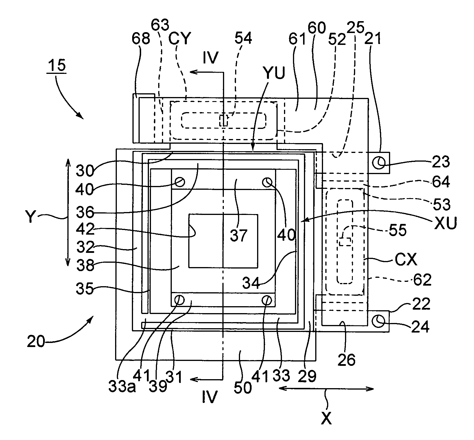
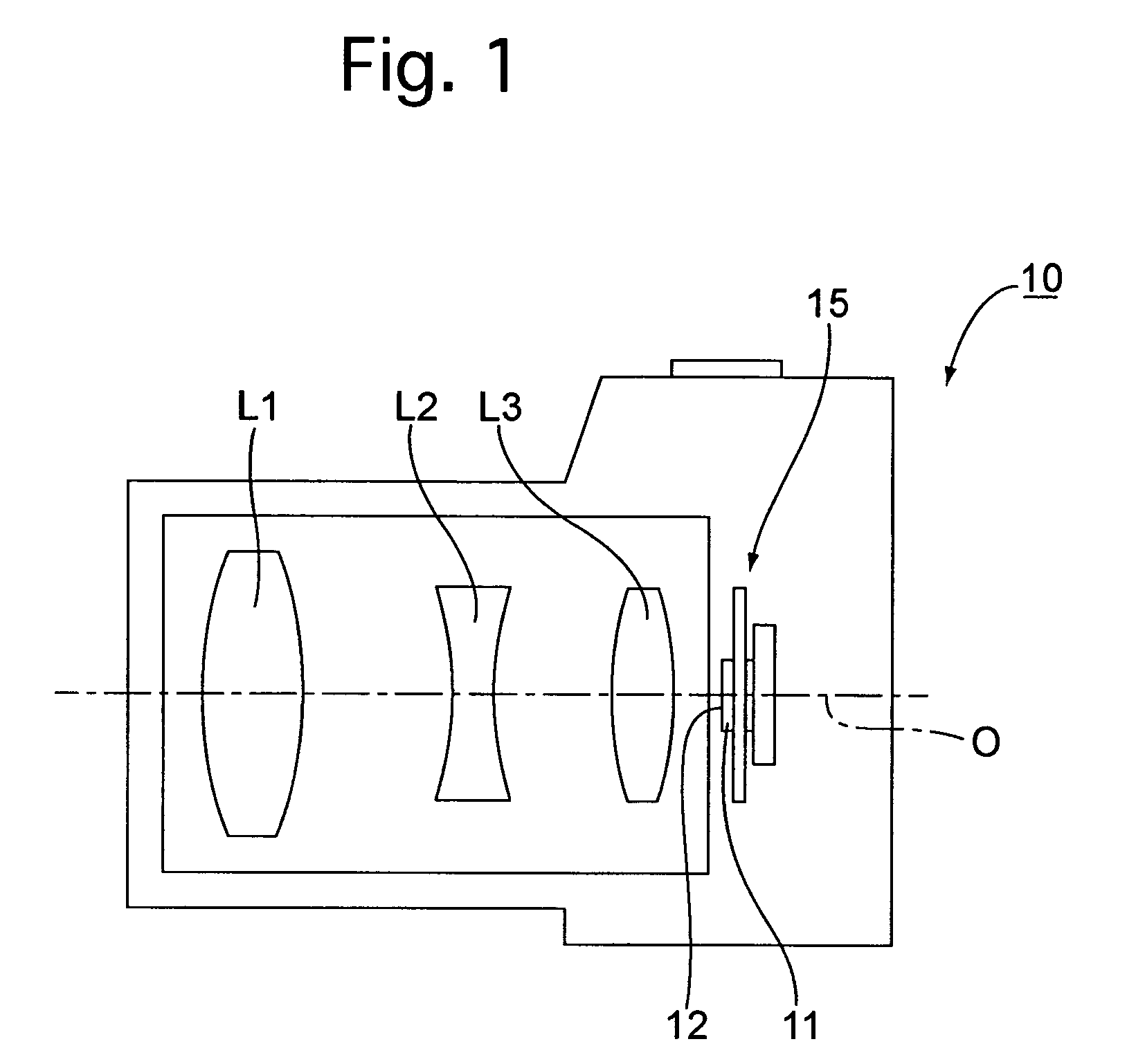
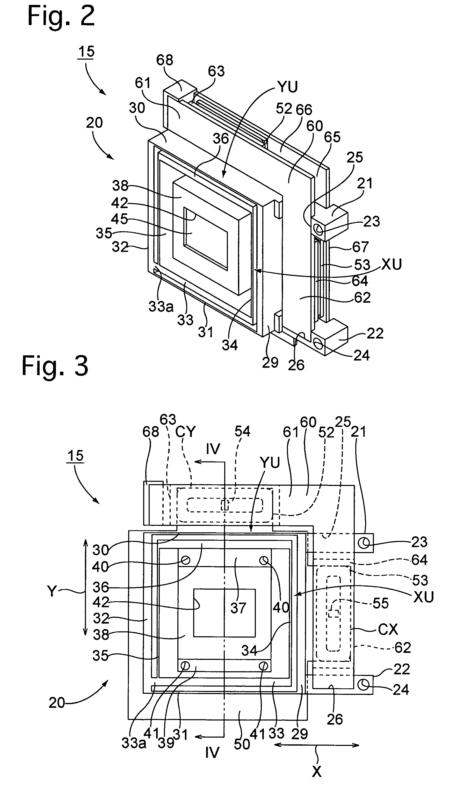
[0082]a camera shake correction apparatus (image stabilizer) according to the present invention will be hereinafter discussed with reference to FIGS. 1 through 11. The camera shake correction apparatus 15 is incorporated in a digital camera 10 (stationary body) as shown in FIG. 1.

[0083]As shown in FIG. 1, the digital camera 10 is provided therein with a photographing optical system including a plurality of lenses L1, L2 and L3. An image pickup device (e.g., CCD or CMOS image sensor) 11 is provided behind the lens L3. The image pickup device 11 is provided with an imaging surface (image-forming plane) 12 which is located on an image plane of the photographing optical system and is perpendicular to an optical axis O of the photographing optical system. The image pickup device 11 is secured to the camera shake correction apparatus 15 that is incorporated in the digital camera 10.

[0084]The camera shake correction apparatus 15 is constructed as described in the following description with...

second embodiment

[0129]Likewise with the stage apparatus 100 incorporated in the camera shake correction apparatus shown in FIGS. 14 through 19, the stage apparatus 100 shown in FIG. 24 can be formed as one body by insertion molding, wherein the first U-shaped leaf spring 110 and the second U-shaped leaf spring 115 are set in a molding die (not shown) in advance. The movable support side-member 32 substantially linearly moves in the Y-direction relative to the stationary support side-member 29 to correct camera shake in the Y-direction by resilient deformation of each of the pair of X-direction leaf springs 111 and 112 in the shape of a letter S as viewed in the Z-direction, while the connecting member 36 substantially linearly moves in the X-direction relative to the support member 33 to correct camera shake in the X-direction by resilient deformation of each of the pair of Y-direction leaf springs 116 and 117 in the shape of a letter S as viewed in the Z-direction. Note that a reinforcing element ...

third embodiment

[0130]the camera shake correction apparatus (image stabilizer) according to the present invention will be hereinafter discussed with reference to FIGS. 25 through 29. Elements and portions of this embodiment of the camera shake correction apparatus which are similar to those of the second embodiment of the camera shake correction apparatus shown in FIGS. 14 through 19 are designated by the same reference numerals, and detailed descriptions of such similar elements and portions are omitted from the following descriptions.

[0131]The third embodiment of the camera shake correction apparatus is the same as the second embodiment of the camera shake correction apparatus except that a stage apparatus 300 in the third embodiment of the camera shake correction apparatus is different in structure from the stage apparatus 100 in the second embodiment of the camera shake correction apparatus, and accordingly, only the stage apparatus 300 will be discussed thereinafter.

[0132]The stage apparatus 3...


PUM


Abstract

A stage apparatus includes a Y-direction deformable body including a stationary support member, a movable support member and a pair of X-direction leaf springs to form a substantially rectangular shape in a free state; and an X-direction deformable body, positioned in the Y-direction deformable body, including a connecting member, a support member and a pair of Y-direction leaf springs to form a substantially rectangular shape in a free state. The support member of the X-direction deformable body includes a support member joint portion which joins the support member to the movable support member of the Y-direction deformable body. The X-direction deformable body and the Y-direction deformable body are integrally molded by synthetic resin together with the support member joint portion.

Description

BACKGROUND OF THE INVENTION[0001]1. Field of the Invention[0002]The present invention relates to a stage apparatus for substantially linearly moving a movable stage, that supports an image pickup device (e.g., CCD image sensor), in two orthogonal directions on a plane, and a camera shake correction apparatus using such a stage apparatus.[0003]2. Description of the Prior Art[0004]A known stage apparatus used as a camera shake correction apparatus in which a movable stage is substantially linearly moved in two orthogonal directions in a plane is described in, for example, Japanese laid-open patent publication H6-46314.[0005]Such a known stage apparatus (shake correction apparatus) is provided with a square frame member having an inside space in which an X-direction driving system (first drive system) and a Y-direction driving system (second drive system) are installed. The X-direction driving system is composed of a pair of Y-direction leaf springs (parallel leaf springs) which extend...

Claims


Application Information

Patent Timeline
Patent Type & Authority Patents(United States)
IPC IPC(8): G03B17/00
CPCG03B5/00H04N5/2253H04N5/23248H04N5/23287G03B2205/0007G03B2217/002H04N23/54H04N23/68H04N23/687
Inventor ENOMOTO, SHIGEO
Owner RICOH IMAGING COMPANY
Why Eureka
Try Eureka