Gun sight and method for hitting a moving target

a technology of moving targets and gun sight, which is applied in the direction of aiming means, sighting devices, weapons, etc., can solve the problems of difficult to estimate the size of lead angle to provide, the use of gun sight is much less for hunting real game, and the problem of moving target problems is more difficul

Inactive Publication Date: 2008-02-12
DIETZ GREGORY D
View PDF26 Cites 24 Cited by
  • Summary
  • Abstract
  • Description
  • Claims
  • Application Information

AI Technical Summary

Benefits of technology

[0009]The present invention provides an aiming mechanism and method that provide a plurality of different-sized target alignment indicia extending out in at least one direction from the barrel of a gun, wherein larger-sized artifacts, used to align to closer targets, are placed closer to the barrel of the gun since those closer objects require less leading. By matching the size of the artifact to the apparent size of the moving target, the distance to the target can be compensated for, and the proper amount of lead (the angle for pointing the barrel relative to the target) can be provided for targets of any given distance. By providing different customized sights for targets having different inherent speeds, the appropriate amount of lead can be matched to the speed of the target. Thus, a sight used for hunting pheasants can be customized such that the various different sized artifacts used to estimate distance to the pheasant target can be spaced apart by an amount that also takes into account the average flying speed of a pheasant. Further, a sight used for hunting fast-flying ducks can be customized such that the various different sized artifacts used to estimate distance to the duck target can be spaced apart by an amount that also takes into account the average flying speed of a fast-flying duck.

Problems solved by technology

Moving targets present a more difficult problem.
With prior-art sights, it has been quite difficult to estimate the size of lead angle to provide.
While perhaps useful for skeet where the target is always at a fixed distance, such a gun sight is much less useful for hunting real game where the target is at various ranges and differing speeds.
This would be a difficult judgment task for a hunter in the field hunting real game where the target is at various ranges and differing speeds.
This device also leaves the marksman with the problem of judging distance to the object and its speed.

Method used


Image

  • Gun sight and method for hitting a moving target
  • Gun sight and method for hitting a moving target
  • Gun sight and method for hitting a moving target

Examples


Embodiment Construction

[0054]In the following detailed description of the preferred embodiments, reference is made to the accompanying drawings that form a part hereof, and in which are shown by way of illustration specific embodiments in which the invention may be practiced. It is understood that other embodiments may be utilized and structural changes may be made without departing from the scope of the present invention.

[0055]The leading digit(s) of reference numbers appearing in the Figures generally corresponds to the Figure number in which that component is first introduced, such that the same reference number is used throughout to refer to an identical component which appears in multiple Figures. The same reference number or label may refer to signals and connections, and the actual meaning will be clear from its use in the context of the description.

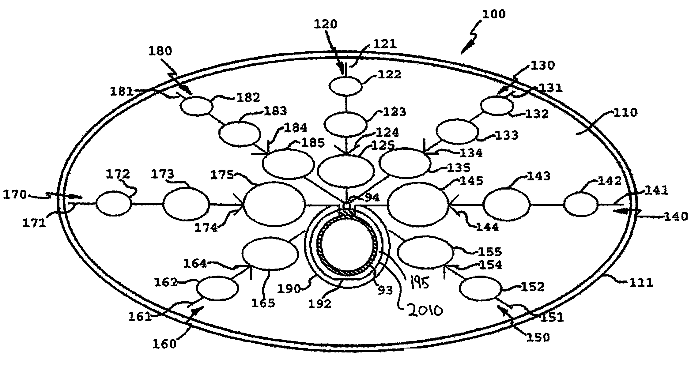
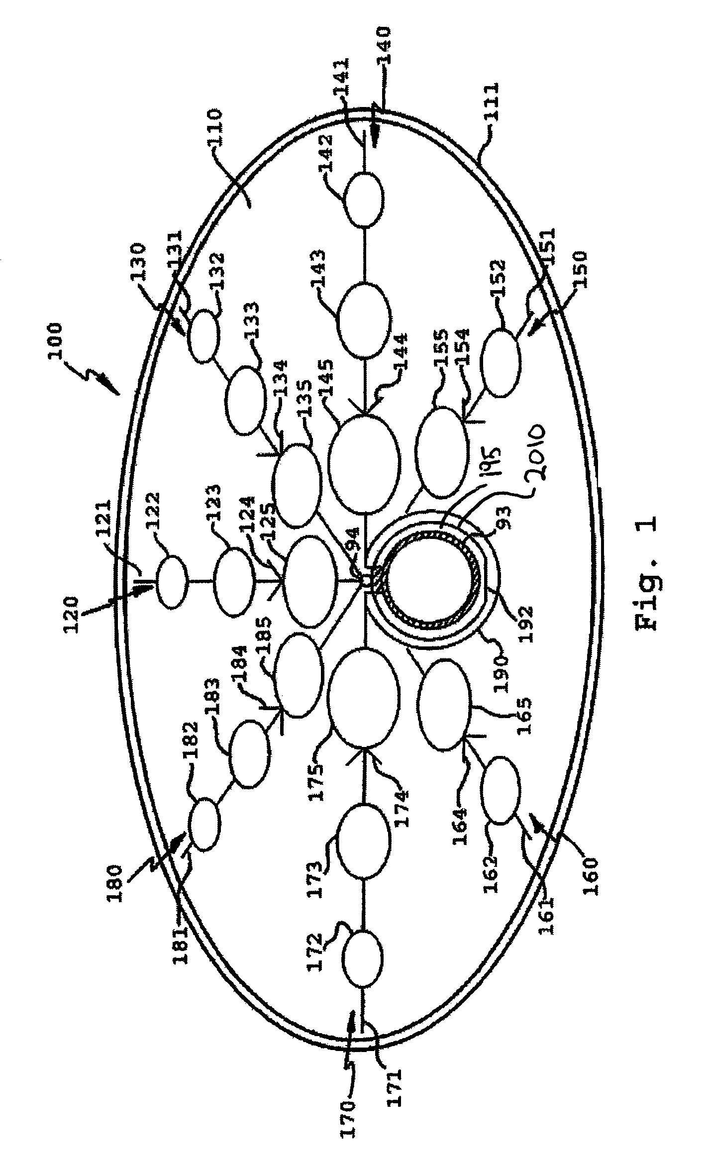
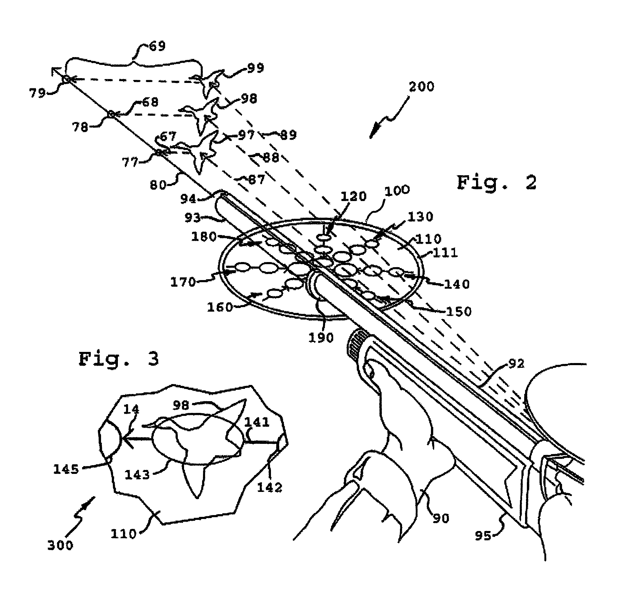
[0056]The gun sight of the present invention has been developed to assist shooters in determining the appropriate lead when shooting a moving target. T...


PUM


Abstract

A method and apparatus for configured to be attached to a gunbarrel of a firearm helping to aim at a moving target. The gun sight includes different-sized sight indicators including a first sight indicator located to be closer to the gunbarrel, and a second sight indicator, smaller than the first sight indicator and located to be further from the gunbarrel, both along a first direction that extends from the gunbarrel. In some embodiments use a plurality of different-sized of sight indicators along each of a plurality of directions for tracking moving targets approximately in those directions, for helping determine the amount of lead (the angle between the gunbarrel and the line to the target) used when shooting. Some embodiments use indicators, such as printed or embossed lines, icons, or tinted shapes, on a transparent substrate, while others use a wire-like structure formed with the indicators. Some embodiments use an anti-reflective coating.

Description

FIELD OF THE INVENTION[0001]This invention relates to the field of firearm aiming, and more specifically to a method and apparatus for assisting aiming a gun to appropriately lead a moving target.BACKGROUND OF THE INVENTION[0002]Firearms have been used by people for centuries. Aiming aids such as sights, crosshairs, or telescopes have been added to various firearms to assist the shooter in pointing the gun at a target.[0003]Since the projectiles shot from a gun have a limited velocity, they drop in a curve (typically an asymmetric parabolic curve). Thus, when shooting at a stationary target, the sight on a gun will be set to aim the barrel (i.e., a straight line extending from the axis of the barrel) above the target by an amount that compensates for the drop in the projectile as it travels the distance to the target.[0004]Moving targets present a more difficult problem. Since the target will have moved some distance left, right, up, or down (and perhaps closer or further away) betw...

Claims


Application Information

Patent Timeline
Patent Type & Authority Patents(United States)
IPC IPC(8): F41G3/14F41G1/473
CPCF41G1/473
Inventor DIETZ, GREGORY D.
Owner DIETZ GREGORY D
Why Eureka
Try Eureka