Refrigerant valve arrangement

a technology for refrigerant valves and housings, which is applied in the direction of water supply installation, fluid pressure control, lighting and heating apparatus, etc., can solve the problem of not fixing the housing arrangement in space, and achieve the effect of facilitating manufactur

Inactive Publication Date: 2008-02-12
DANFOSS AS
View PDF26 Cites 10 Cited by
  • Summary
  • Abstract
  • Description
  • Claims
  • Application Information

AI Technical Summary

Benefits of technology

[0006]This arrangement makes it possible, by relatively simple means, for more than one functional element at the same time to be accommodated in the housing. The two functional elements are simply arranged on sides of the internal boundary wall which are located opposite one another. This is possible without any problems because appropriate contact surfaces are provided on both sides of the internal boundary wall. Communication between the first functional space and the second functional space is provided by the channel which passes through the internal boundary wall.
[0009]In this arrangement it is preferred that of four functional spaces of two neighbouring pairs, at least three functional spaces are provided with a functional element. It is, accordingly, not necessary for all the functional spaces to be equipped with a functional element. However, it is advantageous if more than half of the functional spaces are provided with functional elements.
[0010]It is also advantageous when all the functional spaces are serially arranged. This results in the same refrigerant flow through all the functional spaces and, as a result, through all the functional elements arranged in the functional spaces.
[0013]Preferably, the top external wall is, at the outlets from the first functional spaces, provided with an annular bead in each case. A fastening surface can then be produced on the annular bead without having to machine the entire outside of the external wall.
[0014]Preferably, the second contact surface has a ring-like projection, which surrounds the channel. This also facilitates manufacture. When the second contact surface is, for example, to take the form of a valve seat, it is simpler to machine the ring-like projection than the entire side of the boundary wall which bounds the second functional space.

Problems solved by technology

When here and hereinbelow terms such as “bottom” and “top” are used they do not fix the arrangement of the housing in space.

Method used


Image

  • Refrigerant valve arrangement
  • Refrigerant valve arrangement
  • Refrigerant valve arrangement

Examples


Embodiment Construction

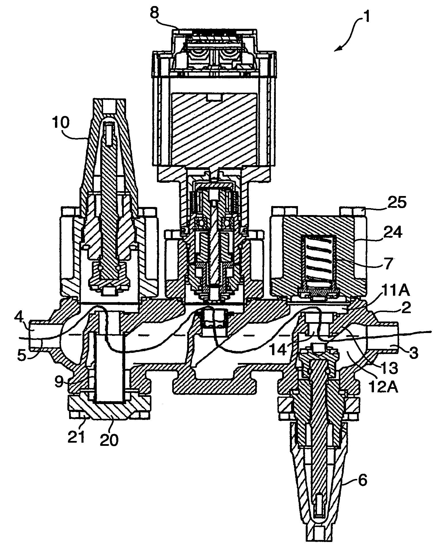
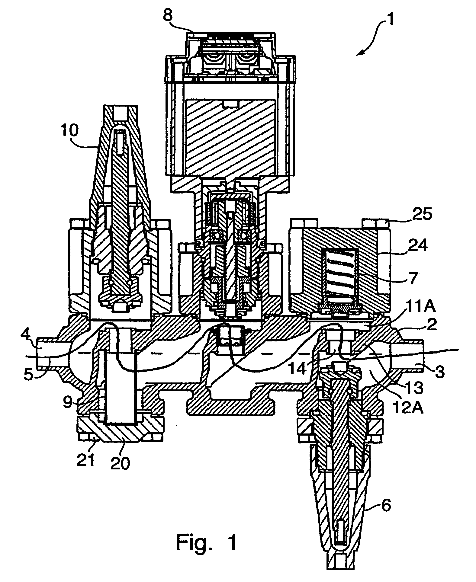
[0022]A refrigerant valve arrangement 1 has a housing 2 having an inlet 4 and an outlet 3. Provided between the inlet 4 and the outlet 3 is a flow path 5 (shown by an unbroken line) for refrigerant. For controlling the flow of the refrigerant through the valve arrangement 1 there are provided various functional elements, all of which are inserted in the housing 2.

[0023]Firstly, the refrigerant is controlled by a shut-off valve 10, which closes off the flow path 5 at the inlet 4. Following on therefrom in the flow path 5 is a filter 9. From the filter 9, the flow path 5 proceeds to a throttle valve 8. The throttle valve 8 performs the actual control of the refrigerating system. From the throttle valve 8, the flow path proceeds through a free space in the housing to a non-return valve 7 and from there to a second shut-off valve 10, which is arranged at the outlet 3 from the housing 2. By means of the two shut-off valves 6, 10, the valve arrangement 1 can be completely isolated from th...


PUM


Abstract

A refrigerant valve arrangement is described, having a housing which has a first functional space, in which there is arranged at least one functional element, which co-operates with a first annular contact surface formed in an internal boundary wall. It is desirable to be able to match a refrigerant valve arrangement to different functions with little outlay. For that purpose there is provided, arranged on that side of the boundary wall which is located opposite the first functional space, a second functional space, in which a second functional element can be positioned and which has a second annular contact surface, a channel which passes through the boundary wall opening out in both contact surfaces.

Description

CROSS-REFERENCE TO RELATED APPLICATIONS[0001]This application is entitled to the benefit of and incorporates by reference essential subject matter disclosed in German Patent Application No. 103 58 085.9 filed on Dec. 10, 2003.FIELD OF THE INVENTION[0002]The invention relates to a refrigerant valve arrangement having a housing which has a first functional space, in which there is arranged at least one functional element, which co-operates with a first annular contact surface formed in an internal boundary wall.BACKGROUND OF THE INVENTION[0003]A valve arrangement of such a kind, which is also provided for refrigerant, is known from U.S. Pat. No. 4,550,896. The housing is, in that case, so arranged that various functional elements can be inserted. The functional elements can be, for example, valve elements which co-operate with a valve seat formed on the contact surface. They can consist of a strainer which is in contact with the contact surface or they can consist of a non-return valv...

Claims


Application Information

Patent Timeline
Patent Type & Authority Patents(United States)
IPC IPC(8): F25B41/06E03B1/00F16K27/00F25B41/04
CPCF16K27/003F25B41/04Y10T137/7043Y10T137/87917F25B41/20
Inventor WIWE, JOERGEN SEINDALMICHELSEN, KENNETHDENNING, LARS
Owner DANFOSS AS
Why Eureka
Try Eureka