Cushioning material for packaging and packaging matter

a technology of packaging and material, applied in the direction of packaging, special packaging, packaged goods, etc., can solve the problem of troublesome operation, and achieve the effect of convenient replacemen

Inactive Publication Date: 2008-02-12
SEIKO EPSON CORP
View PDF32 Cites 21 Cited by
  • Summary
  • Abstract
  • Description
  • Claims
  • Application Information

AI Technical Summary

Benefits of technology

[0015]According to the constructions described above, the upper pad side hollow convex portions or the lower pad side hollow convex portions are reinforced by the upper side reinforcing plate portions of the upper spacer or the lower side reinforcing plate portions of the lower spacer. Therefore, even when impact is applied, the upper pad side hollow convex portions or the lower pad side hollow convex portions are not broken, but instead reliably protect the article to be packaged from the impact.
[0037]When the sidewall portion of the lower pad is recessed inward to thereby define a step portion capable of arranging the accessory in the recessed portion, a window for charging the accessory in the recessed portion is preferably formed in the side surface of the corrugated cardboard box. When the accessory accommodation box having the charge port capable of putting the instruction manual into, and taking it out from, the tray is used as the accessory accommodation body, a window for charging the accessory into the charge port is preferably formed in he side surface of the corrugated cardboard box. According to this construction, the accessories such as the power source cable and the instruction manual can be easily replaced even after packaging is completed.

Problems solved by technology

In the packaging structure shown in FIG. 24, however, it is necessary to unpack the package and to take out the instruction manual from the accessory accommodation box 6 for replacement after the projector is completely packaged for export procedures or the like, and this operation is very troublesome.

Method used


Image

  • Cushioning material for packaging and packaging matter
  • Cushioning material for packaging and packaging matter
  • Cushioning material for packaging and packaging matter

Examples


embodiment 2

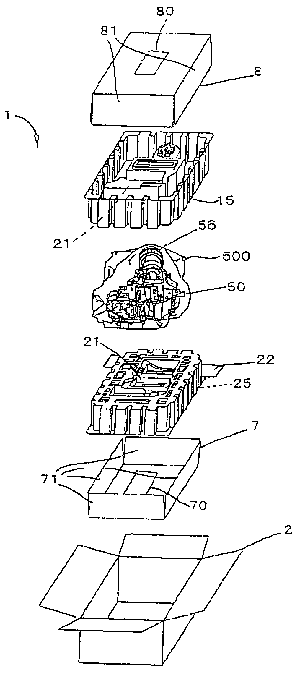
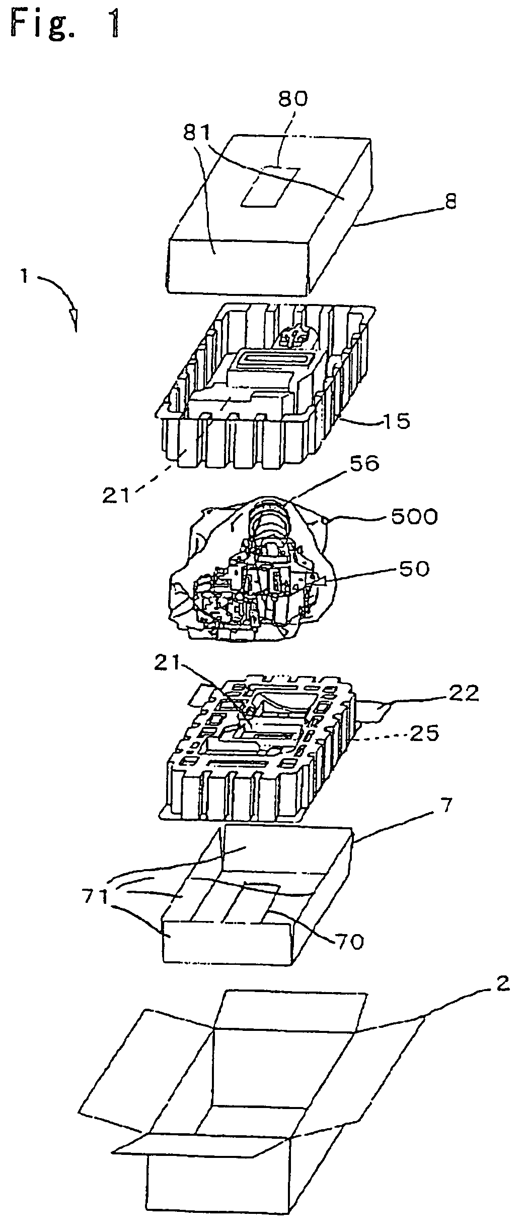
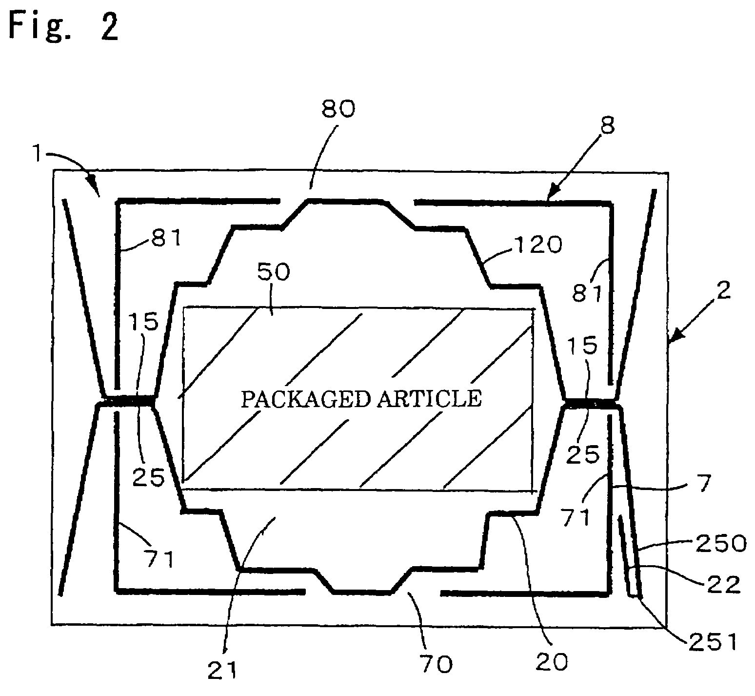
[0075]FIGS. 4A and 4B are respectively a sectional view showing a mode of packaging a projector (an electronic apparatus) as an article to be packaged in a corrugated cardboard box using a cushioning material for packaging according to Embodiment 2 of the invention, and a sectional view showing in magnification an overlap portion between an upper-pad-side hollow convex portion 15 and a lower-pad-side hollow convex portion 25. FIG. 5 is a perspective view showing an example of a lower pad used in the cushioning material for packaging in this embodiment. Since the cushioning material for packaging according to this embodiment has fundamentally the same construction as that of Embodiment 1, like reference numerals will be used to identify portions having common functions and their explanation will be omitted.

[0076]To package the projector 50 in the corrugated cardboard box 2 (a discrete box), in this embodiment, too, the lower spacer 7 formed of corrugated cardboard, the lower pad 20 f...


PUM

PropertyMeasurementUnit
thicknessaaaaaaaaaa
thicknessaaaaaaaaaa
timeaaaaaaaaaa

Abstract

The invention provides a cushioning material for packaging that is suitable for packaging an electronic apparatus, an optical apparatus or an electronic apparatus having an optical system mounted therein, and a package that uses the cushioning material for packaging. In the invention, a lower spacer formed of corrugated cardboard, a lower pad, a projector as an article to be packaged that is wrapped in an anti-static bag having electrical conductivity, an upper pad and an upper spacer formed of a corrugated cardboard can be stacked inside a corrugated cardboard box. The upper and lower pads are, respectively, provided with a plurality of upper pad side hollow convex portions and a plurality of lower pad side hollow convex portions protruding in such a fashion as to encompass an accommodation space for the projector. Upper and lower side reinforcing plate portions of the upper and lower spacers, respectively, enter deep into these convex portions.

Description

BACKGROUND OF THE INVENTION[0001]1. Field of Invention[0002]This invention relates to a cushioning material for packaging that is suitable for packaging an electronic apparatus, an optical apparatus or an electronic apparatus having an optical system mounted therein, and a package using this cushioning material for packaging.[0003]2. Description of Related Art[0004]An electronic apparatus having an optical system mounted therein, such as a projector, must be protected from being damaged by impact from the outside during transportation while the apparatus is packaged into a corrugated cardboard box. For example, a cushioning material for packaging that has an upper pad 10 and a lower pad 20 as shown in FIGS. 21 and 22, has been used in the past. A lower stiffening plate 3 formed of a corrugated cardboard, a lower pad 20, a projector 50 as an article to be packaged (or an optical engine mounted in the projector) that is wrapped by an anti-static bag 500, an upper pad 10 and an upper s...

Claims


Application Information

Patent Timeline
Patent Type & Authority Patents(United States)
IPC IPC(8): B65D81/02B65D81/113B65D5/50B65D5/58B65D77/04B65D81/133
CPCB65D5/5088B65D5/58B65D77/042B65D81/025B65D81/133B65D2585/6835
Inventor KOIKE, MOTOMU
Owner SEIKO EPSON CORP
Why Eureka
Try Eureka