Interior rearview mirror system with compass

a technology for rearview mirrors and mirror assemblies, which is applied in the direction of optical elements, instruments, transportation and packaging, etc., can solve the problems of high cost of compass mirror assemblies, inability to adapt to use with double ball or double pivot mirror assemblies, and special tooling of compass systems described in the patents referenced above, so as to reduce the effect of mirror adjustment on the performance of compass sensors, reduce the effect of such items on the compass sensor performance, and reduce the effect of mirror

Inactive Publication Date: 2008-02-12
DONNELLY CORP
View PDF67 Cites 200 Cited by
  • Summary
  • Abstract
  • Description
  • Claims
  • Application Information

AI Technical Summary

Benefits of technology

[0008]According to an aspect of the present invention, a mirror and compass system includes an interior rearview mirror assembly having a reflective element and a casing that are adjustable relative to a mounting structure. A compass sensor having at least two magnetoresponsive sensing elements is positioned within the mirror casing and at a position and orientation that reduces the effect of adjustment of the mirror on the compass sensor output.
[0009]The compass sensor is preferably positioned at a generally central location of the mirror and at or near the centerline of the mirror head. Preferably, the compass sensor is positioned at or near a lower region of the mirror casing to position the sensor remotely from the roof of the vehicle and any wiring or lights or the like that may be positioned at the roof of the vehicle, in order to reduce the effect of such items on the compass sensor performance.
[0010]Preferably, the compass sensor is oriented such that one of the sensing elements is generally along a longitudinal axis of the vehicle and the other sensing element is generally along a cross car axis of the vehicle when the mirror is oriented at a typical in-use position (such as at an angle of about 20 degrees rotation toward the driver side and at an angle of about 9 degrees tilt downward). Optionally, the system may determine when a prismatic mirror is flipped or toggled between the daytime and nighttime orientations and may compensate or adjust the processing of the compass sensor output to compensate for the known movement (such as about 4½ degrees upward or downward) of the mirror head / reflective element and compass sensor.
[0011]Optionally, the compass sensor may be positioned in close proximity to the mirror ball of the mounting arm (the ball that is received in the socket at the mirror casing or reflective element or toggle portion of the mirror assembly) so as to reduce movement of the compass sensor when the mirror is adjusted, in order to reduce the effects of mirror adjustment on the compass sensor performance. Optionally, the compass sensor may be generally fixedly positioned relative to the mirror ball of the mounting arm so that the compass sensor is generally fixed and do not move during adjustments of the mirror head / reflective element when the driver grasps and moves the mirror head / reflective element to adjust to his or her preferred field of view rearward through the rear window of the vehicle.
[0012]Optionally, the mirror and compass system may operate to enter a rapid compensating and aggressive calibration mode in response to a detection of an abrupt movement of the mirror head and compass sensor. The system may determine when such an abrupt movement is indicative of a mirror adjustment (such as an adjustment between the daytime and nighttime orientations for a prismatic mirror or an adjustment of the mirror by a person who has just entered the vehicle or started the vehicle ignition), and then may enter the aggressive calibration mode in response to such a determination. The system thus may discern, such as algorithmically via software and / or aided via a movement / mechanical adjust detector / sensor element, between a change in sensor output that is indicative of a mirror adjustment and a change in sensor output that is indicative of a change in vehicle direction and may enter the aggressive calibration mode when the change in sensor output is indicative of a mirror adjustment. Such a mirror adjustment typically occurs rapidly (such as in less than one second) and has a predictable range and / or direction, so that the compass system can discern when a change in sensor output is indicative of a mirror adjustment versus a detection of a magnetic field anomaly or the like or versus a change in directional heading of the vehicle.
[0015]Therefore, the present invention provides a mirror and compass system that positions the compass sensor within the movable head portion of the mirror assembly. The compass sensor is positioned in a manner that reduces the effects of mirror adjustment on the sensor performance. The system may adjust processing in response to known movements of the mirror head to compensate for such known movements. The system may enter an aggressive calibration mode to calibrate the compass sensor when the mirror has been adjusted by a user. The compass system may distinguish between the anomaly signature or pattern and the mirror adjustment signature or pattern and may enter the calibration mode when the mirror adjustment is detected.

Problems solved by technology

Such compass mirror assemblies can be costly and often involve special tooling and complicated adaptation of the mirror assembly itself and the casing of the mirror assembly.
Also, such compass systems as described in the patents referenced above are not readily adapted for use with double ball or double pivot mirror assemblies.
WO 2003 / 074969 A3, published Sep. 12, 2003 (which are all hereby incorporated herein by reference), may be implemented in interior rearview mirror assemblies, but may be costly and difficult to implement within the movable mirror head of an interior rearview mirror assembly with a single or double ball mounting arrangement.

Method used


Image

  • Interior rearview mirror system with compass
  • Interior rearview mirror system with compass
  • Interior rearview mirror system with compass

Examples


Embodiment Construction

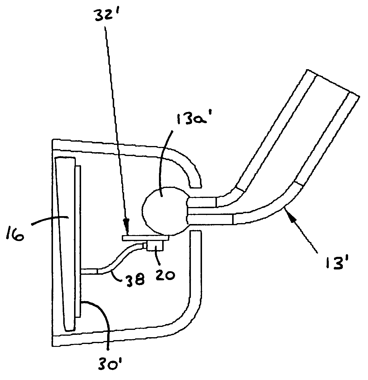
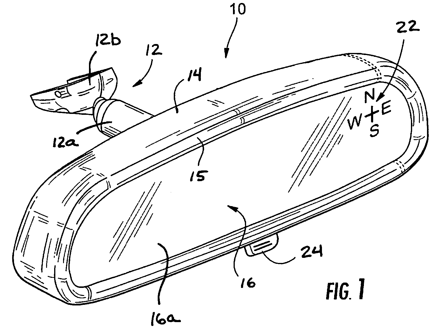
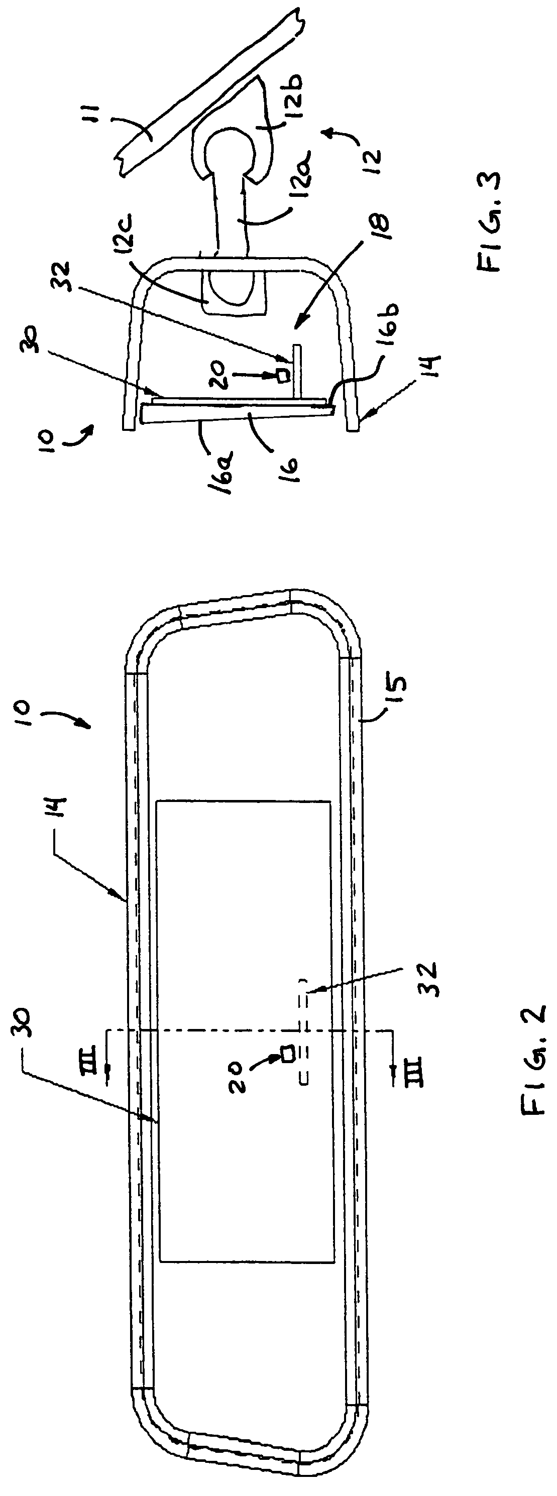
[0024]Referring now to the drawings and the illustrative embodiments depicted therein, a compassized prismatic interior rearview mirror assembly or system 10 includes a double pivot or double ball mounting arrangement 12 for pivotally or adjustably mounting a casing 14, bezel portion 15 and prismatic reflective element 16 of mirror assembly 10 relative to an interior portion of a vehicle, such as to an interior surface of a windshield 11 of a vehicle or the like (FIGS. 1-3). The mirror assembly 10 includes a compass system 18, which includes a magnetoresponsive compass sensor 20 and a display 22 for providing a display or indication of the directional heading of the vehicle, such as at the reflective element 16 of the mirror.

[0025]The mirror casing or housing 14 may comprise a polypropylene material or the like and is adjustably mounted to a mirror mount (not shown) positioned at an interior portion of a vehicle, such as a mirror mounting button on a windshield of the vehicle or any...


PUM


Abstract

An interior rearview mirror system for a vehicle includes an interior rearview mirror assembly, a casing having a reflective element, a compass sensor and a control. The compass sensor is disposed within the mirror casing and has a first magnetoresponsive sensing element and a second magnetoresponsive sensing element. The control receives a first signal indicative of a magnetic field sensed by the first magnetoresponsive sensing element and a second signal indicative of a magnetic field sensed by the second magnetoresponsive sensing element. The control determines that the casing is adjusted by an occupant of the vehicle in response to a change in the first and second signals being indicative of an abrupt movement of the casing about the mounting structure by an occupant of the vehicle. The control is operable to enter a rapid compensating mode to compensate for the mirror adjustment.

Description

CROSS REFERENCE TO RELATED APPLICATION[0001]The present application claims benefit of U.S. provisional application, Ser. No. 60 / 636,931, filed Dec. 17, 2004, and the present application is a continuation-in-part of U.S. patent application Ser. No. 10 / 456,599, filed Jun. 6, 2003 now U.S. Pat. No. 7,004,593 by Weller et al. for INTERIOR REARVIEW MIRROR SYSTEM WITH COMPASS, now U.S. Pat. No. 7,004,593, which claims the benefit of U.S. provisional applications, Ser. No. 60 / 420,010, filed Oct. 21, 2002; Ser. No. 60 / 398,240, filed Jul. 24, 2002; and Ser. No. 60 / 386,373, filed Jun. 6, 2002, which are all hereby incorporated herein by reference in their entireties.FIELD OF THE INVENTION[0002]The present invention relates generally to interior rearview mirror assemblies for vehicles and, more particularly, to an interior rearview mirror assembly which includes a compass system.BACKGROUND OF THE INVENTION[0003]Interior rearview mirror assemblies which include a directional or compass display ...

Claims


Application Information

Patent Timeline
Patent Type & Authority Patents(United States)
IPC IPC(8): G02B5/08
CPCB60R1/12G01C17/28G01C17/38B60R2001/1215
Inventor BLANK, RODNEY K.SCHIERBEEK, KENNETH L.LYNAM, NIALL R.
Owner DONNELLY CORP
Why Eureka
Try Eureka