Electrical terminal with a spring force clamping terminal for two conductors

a technology of spring force and clamping terminal, applied in the direction of contact members penetrating/cutting insulation/cable strands, electrical apparatus, fastening/insulating connecting parts, etc., to achieve the effect of simple removal and simple insertion of the two conductors

Active Publication Date: 2008-02-12
PHOENIX CONTACT GMBH & CO KG
View PDF20 Cites 36 Cited by
  • Summary
  • Abstract
  • Description
  • Claims
  • Application Information

AI Technical Summary

Benefits of technology

[0012]Therefore, a primary object of this invention is to embody and develop the known electrical terminal such that it has a construction that is as small as possible, and in this connection, enables both simple insertion and also simple removal of the two conductors from the terminal.
[0013]This object is achieved in the initially described type of electrical terminal in that the current bar or bars and the clamping springs are made and arranged such that the current bar or bars are located between the two clamping legs and run essentially parallel to the insertion direction of the conductor to be connected. The arrangement of the current bars or preferably a current bar between the two clamping legs yields a very compact construction of the electrical terminal. Moreover, simultaneous insertion of the two electrical leads to be connected is greatly simplified in that the current bar or bars run parallel to the insertion direction of the conductor to be connected. For the electrical terminal in accordance with the invention, thus, the two electrical conductors to be connected are inserted into the housing from the same direction and pulled out of the housing parallel to one another so that both insertion and also extraction of the two conductors from the housing can be easily done with one hand.
[0017]According to one preferred configuration of the electrical terminal in accordance with the invention, there is at least one actuating pushbutton in the housing which can be moved out of a first position in which the actuating pushbutton does not deflect the clamping leg, into a second position in which the actuating pushbutton deflects the clamping leg against its spring force. In the second position of the actuating pushbutton, the spring force clamping terminal or terminals can thus be opened so that one conductor or the two conductors can be pulled out of or inserted into the terminal.
[0019]Preferably, the electrical terminal in accordance with the invention has simply one actuating pushbutton which is made such that it opens the two spring force clamping terminals at the same time in its second position. Moreover, the actuating pushbutton is made such that conductor inlets for inserting the conductors to be connected together are formed by the housing and the actuating pushbutton. The actuating pushbutton thus has two insert channels for the conductors to be connected. In this way, a further reduction of the dimensions of the electrical terminal is possible since space for accommodating the actuating pushbutton need not be made available in the housing in addition to the conductor inlets.
[0020]In order to facilitate accessibility of the actuating pushbutton even for small dimensions of the electrical terminal, preferably, there is a receiver in the actuating pushbutton which is made for insertion of a tool, especially the tip of a screwdriver. If several electrical terminals next to one another are connected to form a terminal block, actuation of the actuating pushbutton with one finger at contact spacings of 5 mm or less is only possible with difficulty, moreover, there is the danger that the actuating pushbutton of a terminal located next to it is inadvertently actuated at the same time. This problem can be easily solved by the possibility of inserting the tip of a screwdriver into the receiver which is made in the actuating pushbutton.

Problems solved by technology

Moreover, the two electrical conductors to be connected can only be inserted into the electrical terminal at the same time relatively awkwardly and can only be pulled out of the terminal in succession.

Method used


Image

  • Electrical terminal with a spring force clamping terminal for two conductors
  • Electrical terminal with a spring force clamping terminal for two conductors
  • Electrical terminal with a spring force clamping terminal for two conductors

Examples


Embodiment Construction

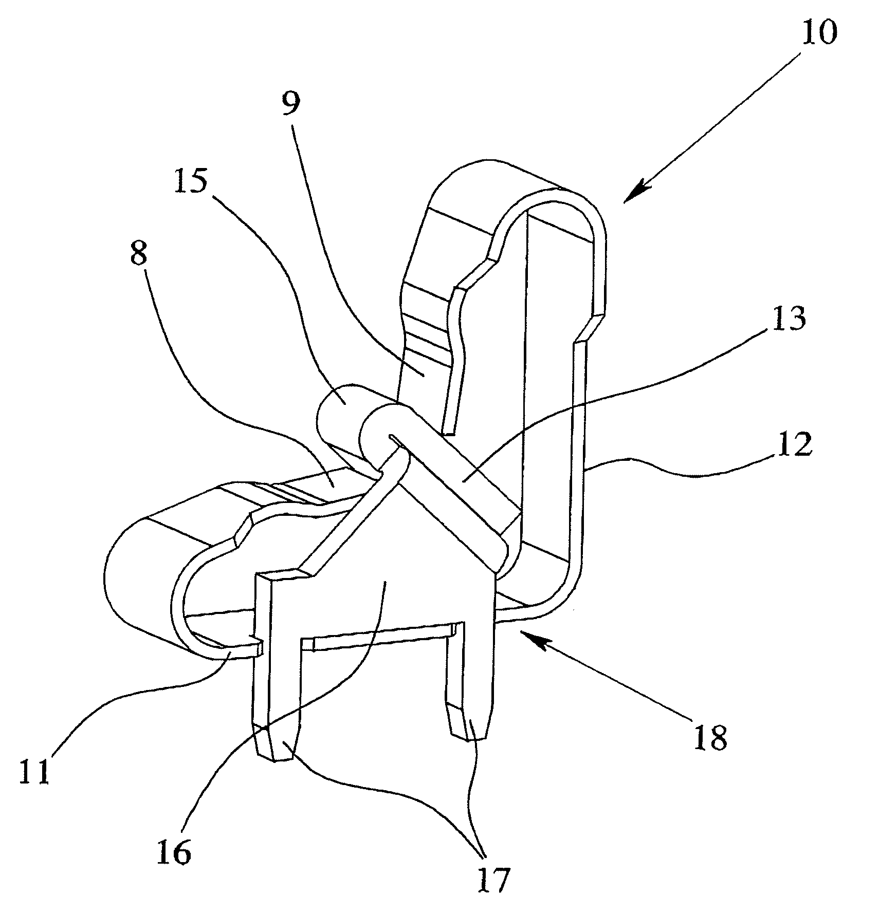
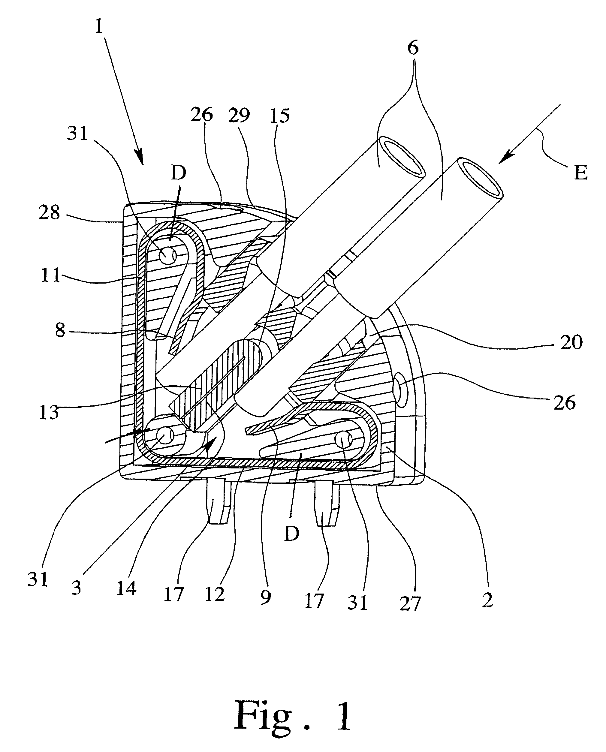
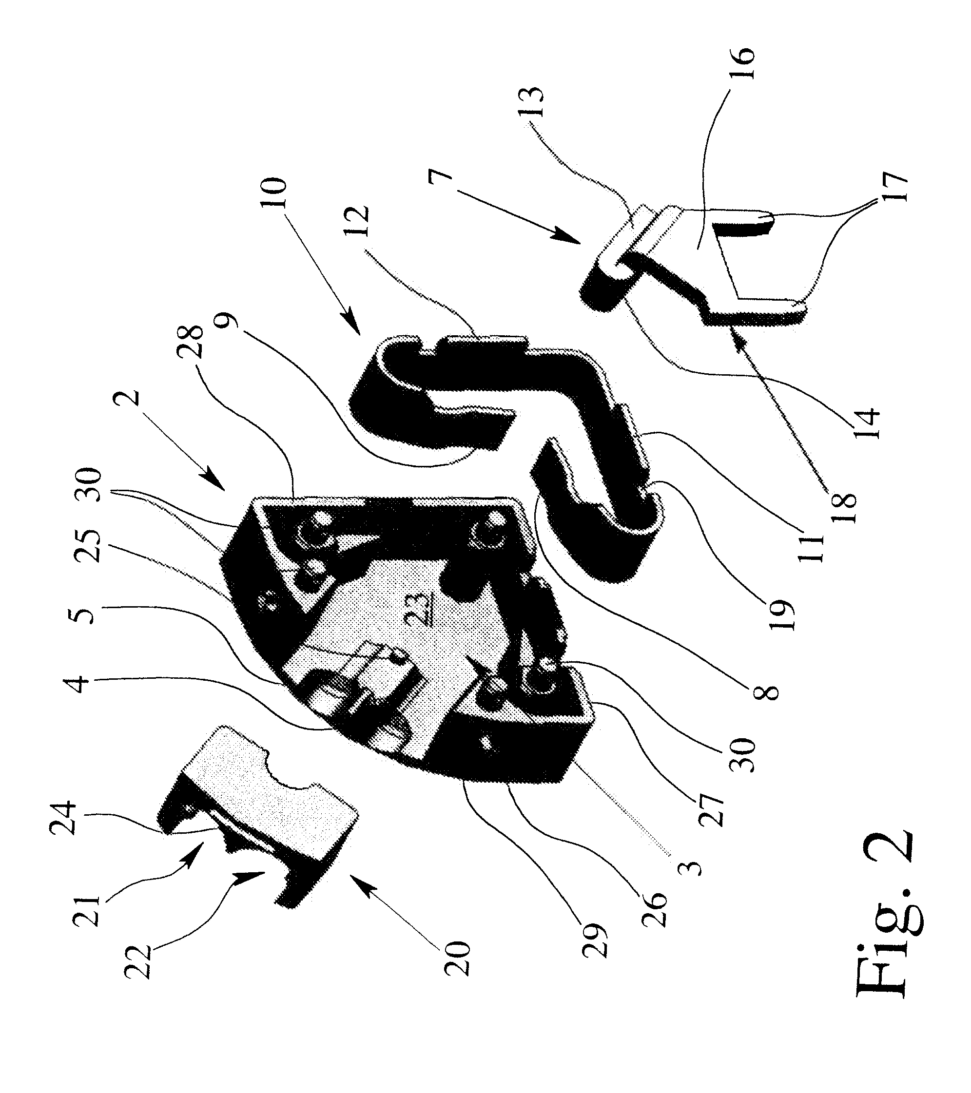
[0026]FIG. 1 shows an electrical terminal 1 with a housing 2 which is made of an insulating material and in which a terminal chamber 3 and two conductor inlets 4, 5, leading into the terminal chamber 3, are formed for two electrical conductors 6 to be connected. In the terminal chamber 3, there is a respective conductor connection arrangement for each conductor inlet 4, 5; the connection arrangements each comprise a current bar 7 and a clamping leg 8, 9, a respective clamping leg 8, 9, forming a spring force clamping terminal for an electrical conductor 6 to be connected together with a facing side of the current bar 7. The two clamping legs 8, 9 are part of a clamping spring 10 which also has two contact legs 11, 12 which, on the one hand, are each connected to a respective clamping leg 8, 9, and on the other hand, are connected to each other. As is apparent from FIG. 1, the two contact legs 11, 12 run essentially perpendicular to one another, the contact legs 11, 12 adjoining an e...


PUM


Abstract

An electrical terminal with a housing having a terminal chamber formed in it, and two conductor inlets which lead into the terminal chamber for electrical conductors to be connected with a respective conductor connection arrangement formed of a current bar and a clamping leg of a clamping spring, the clamping leg and the current bar forming a spring force clamping terminal for an electrical conductor to be connected, and the two clamping legs each being connected to a contact leg. The electrical terminal can have especially small dimensions by there being only one clamping spring in the housing, the two contact legs being connected to one another and adjoining the housing wall on the edge of the terminal chamber, and by the current bar and the clamping springs being made and arranged such that the current bar is located between the two clamping legs.

Description

BACKGROUND OF THE INVENTION[0001]1. Field of the Invention[0002]The invention relates to an electrical terminal with a housing, with a terminal chamber formed in it, and two conductor inlets which lead into the terminal chamber for the electrical conductors to be connected, with one conductor connection arrangement located in the terminal chamber for each conductor inlet, each conductor connection arrangement being formed of a current bar and a clamping leg of a clamping spring, the clamping leg and the current bar forming a spring force clamping terminal for an electrical conductor to be connected, and the two clamping legs each being connected to a contact leg.[0003]2. Description of Related Art[0004]Electrical terminals are used for electrical connection of at least one electrical conductor to a device, especially to a circuit board located in a device. These terminals are often also called printed terminals. In this connection, different electrical terminals are distinguished es...

Claims


Application Information

Patent Timeline
Patent Type & Authority Patents(United States)
IPC IPC(8): H01R11/20H01R4/24H01R4/26
CPCH01R4/4827H01R4/4836H01R12/515H01R4/48365H01R4/48275
Inventor SCHRADER, ANDREAS
Owner PHOENIX CONTACT GMBH & CO KG
Why Eureka
Try Eureka