Method and apparatus for controlling unload standby time of hard disk drive

a technology for hard disk drives and standby time, which is applied in the direction of instruments, data recording, and support for heads, etc., can solve the problems of affecting the stability of data recording, and increasing the possibility of damaging data in both loading and unloading operations. , to achieve the effect of reducing the possibility of damaging data by loading/unloading operations

Inactive Publication Date: 2008-02-12
SAMSUNG ELECTRONICS CO LTD
View PDF13 Cites 3 Cited by
  • Summary
  • Abstract
  • Description
  • Claims
  • Application Information

AI Technical Summary

Benefits of technology

[0018]An aspect of the present invention provides a method of controlling an unload standby time of a hard disk drive according to an accumulated number of unloading operations so that the possibility of damaging data by a loading / unloading operation is reduced.

Problems solved by technology

Indeed, it is preferable to unload the head when the idle state is continued more than a predetermined time so as to reduce power consumption, but it is not preferable, taking performance of HDD into consideration, because an amount of time is needed to load the head being unloaded when leaving from the idle state and there is a high possibility of scratching the disk with the head during both unloading and loading operations.
If the number of loading / unloading operations of an unloading device of a HDD exceeds a designed number, the possibility of the head colliding with the disk increases, thereby data recorded on the disk is damaged in both loading and unloading operations, becomes higher due to abrasion, elastic deterioration, etc. of mechanical parts.
Since a HDD especially adapted to a mobile device suffers frequent loading / unloading operations, the possibility of damaging data increases further as the number of loading / unloading operations increases.
However, in a conventional method of controlling an unload, when duration of the idle state exceeds a predetermined amount of time, an unloading operation is scheduled to perform unconditionally, and thus the possibility of damaging data according to the unloading device with the designed number of loading / unloading operations is not considered at all.

Method used


Image

  • Method and apparatus for controlling unload standby time of hard disk drive
  • Method and apparatus for controlling unload standby time of hard disk drive
  • Method and apparatus for controlling unload standby time of hard disk drive

Examples


Embodiment Construction

[0031]Reference will now be made in detail to embodiments of the present invention, examples of which are illustrated in the accompanying drawings, wherein like reference numerals refer to the like elements throughout. The embodiments are described below in order to explain the present invention by referring to the figures.

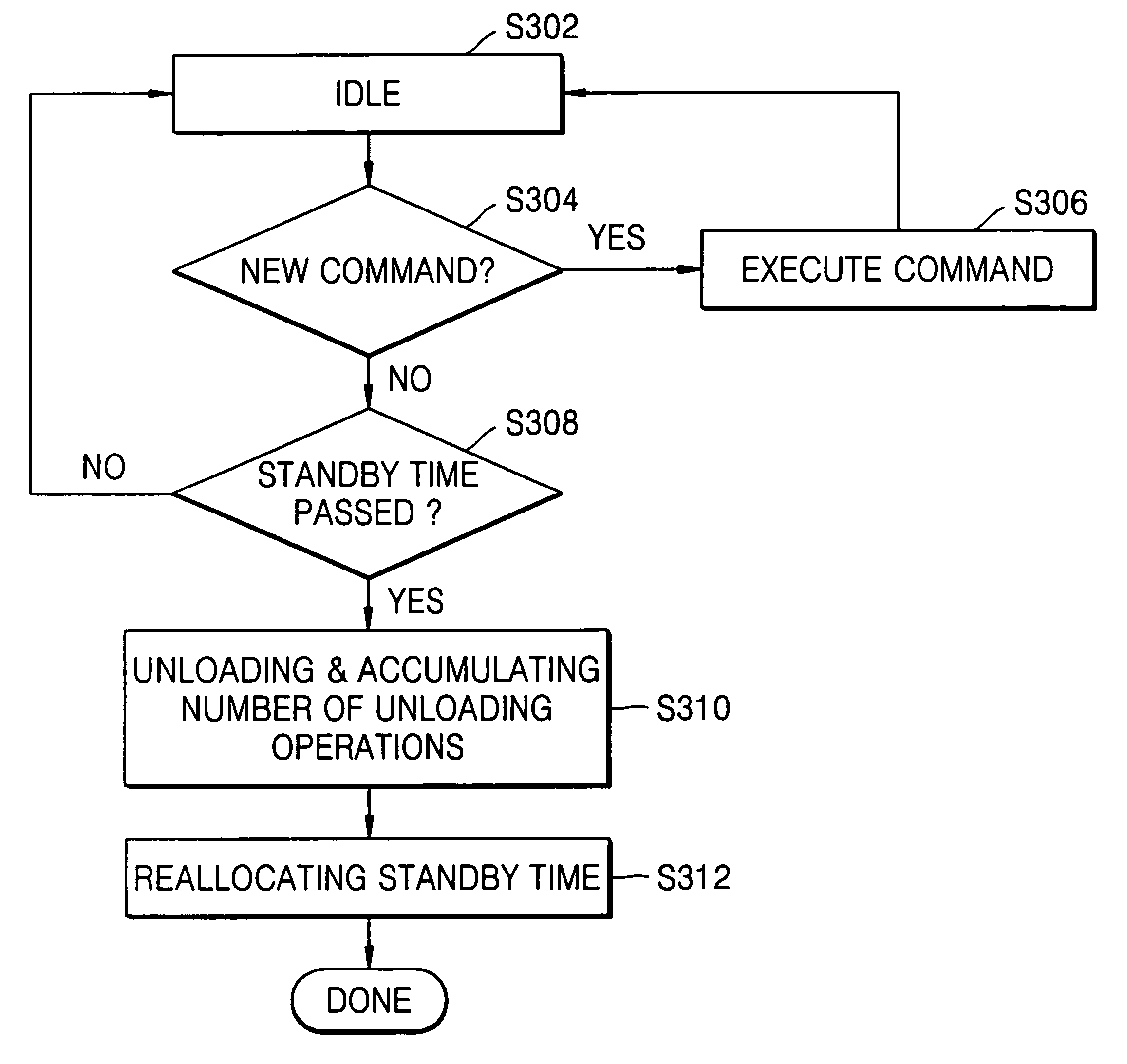
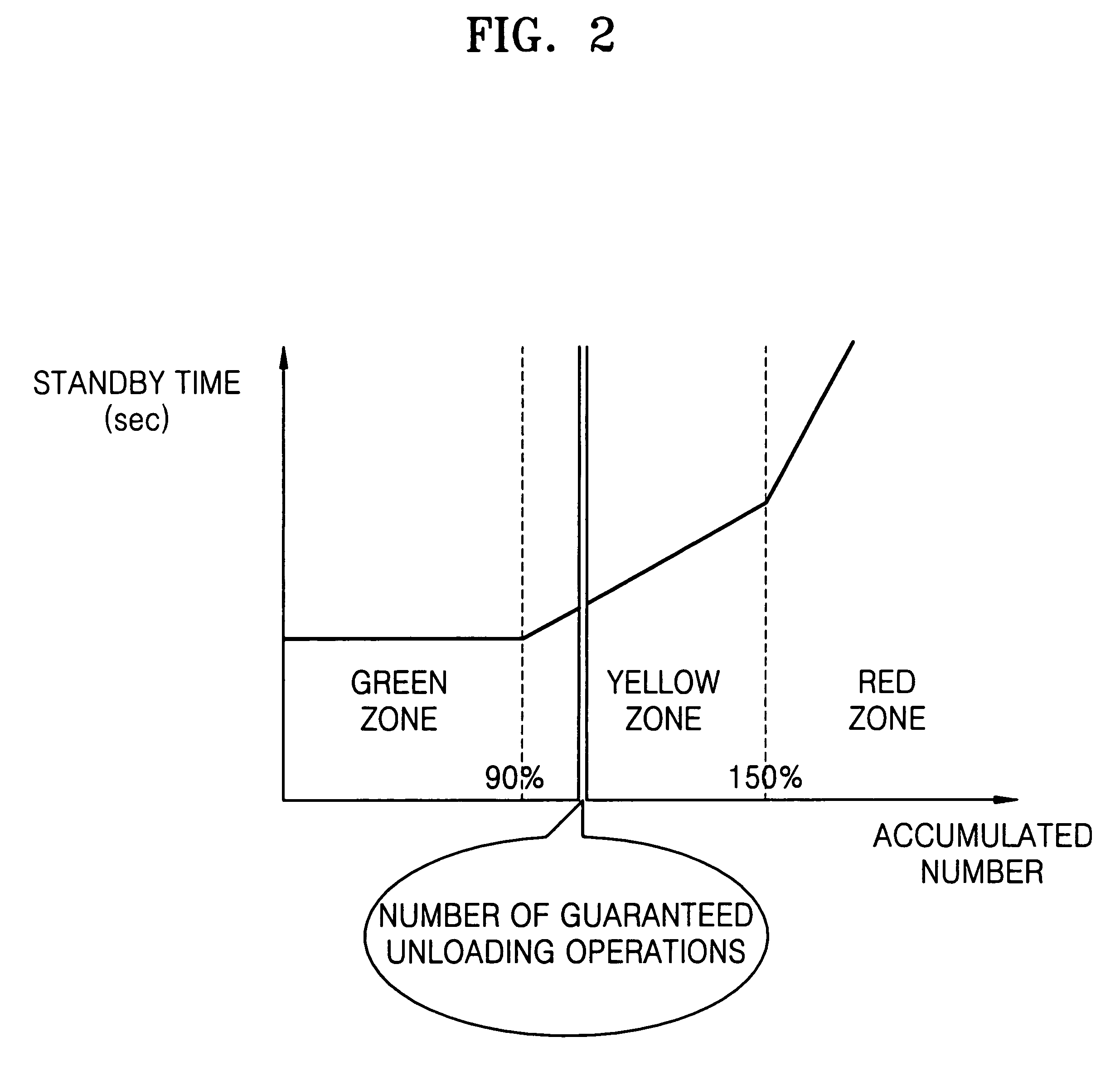
[0032]FIG. 2 is a graph for explaining a method of controlling an unload standby time of a hard disk drive according to an embodiment of the present invention. In FIG. 2, the horizontal axis represents the number of unloading operations, and the vertical axis represents a desired unload standby time. The method of controlling the unload standby time according to an embodiment of the present invention is characterized in that the unload standby time increases as the number of unloading operations increases, as shown in FIG. 2.

[0033]In FIG. 2, the number of guaranteed unloading operations represents the number, of which which a safe unloading operation is guaranteed...


PUM

PropertyMeasurementUnit
unload standby timeaaaaaaaaaa
standby timeaaaaaaaaaa
timeaaaaaaaaaa

Abstract

A method of controlling unloading of a hard disk drive, and more particularly, a method and an apparatus for controlling an unload standby time of a hard disk drive according to the accumulated number of unloading operations. The method includes: standing by for an unload standby time in an idle state of the hard disk drive; unloading a head and then counting the number of unloading operations to determine an accumulated number of unloading operations performed by the hard disk drive after the standby time is passed; and reallocating the unload standby time according to the accumulated number of unloading operations. A standby time for an unloading operation is adjusted according to the accumulated number of unloading operations in a hard disk drive such that the possibility of damaging data is minimized.

Description

CROSS-REFERENCE TO RELATED APPLICATION[0001]This application claims the priority of Korean Patent Application No. 2005-0057133, filed on Jun. 29, 2005, in the Korean Intellectual Property Office, the disclosure of which is incorporated herein by reference.BACKGROUND OF THE INVENTION[0002]1. Field of the Invention[0003]The present invention relates to controlling unloading of a hard disk drive, and more particularly, to a method and an apparatus for controlling an unload standby time of a hard disk drive according to the accumulated number of unloading operations.[0004]2. Description of Related Art[0005]A hard disk drive (HDD) is a recording device used to store information. In general, information is recorded on concentric tracks in a surface of at least one magnetic recording disk. A disk is mounted on a spindle motor to be rotated, and information is accessed by a reading / recording head mounted on an actuator arm rotated by a voice coil motor (VCM). The VCM is excited by current t...

Claims


Application Information

Patent Timeline
Patent Type & Authority Patents(United States)
IPC IPC(8): G11B21/02
CPCG11B19/04G11B19/06G11B21/02G11B21/22
Inventor JUN, JIN-WAN
Owner SAMSUNG ELECTRONICS CO LTD
Why Eureka
Try Eureka