DC-AC converter

a converter and ac technology, applied in the field of electric converters, can solve the problems of increasing energy loss, reducing converting efficiency, energy consumption, etc., and achieve the effects of reducing energy loss, saving cost, and improving converting efficiency

Active Publication Date: 2008-02-12
DELTA ELECTRONICS INC
View PDF9 Cites 28 Cited by
  • Summary
  • Abstract
  • Description
  • Claims
  • Application Information

AI Technical Summary

Benefits of technology

[0014]It is an object of the invention to provide a DC-AC converter applicable for converting a DC input power to an AC output power and regulating a DC input voltage to a just level required by output to effectively reduce energy loss during the DC-AC converter's operation. Also, heavy reservoir capacitors are saved to reduce the cost and increase the converting efficiency.
[0019]In the present invention, due to the utilization of the voltage bypass circuit, if the DC input voltage is high enough to provide AC output power, the voltage boost circuit is not in action and the DC input is transferred to the DC-AC converting module via the voltage bypass circuit. On the contrary, when the DC input voltage is not high enough to provide AC output power, the voltage boost circuit starts to work and regulates the DC input voltage to a level required by output to effectively reduce energy loss during the DC-AC converter's operation. Also and, the high-capacity capacitors can be saved, resulting in saving cost and improvement of the converting efficiency.

Problems solved by technology

1. No matter how the AC power voltage is high or low required by an output end, the DC input power voltage in stage-1 voltage boost circuit must be boosted to its highest voltage. Consequently, the components thereof must be operated or switched in the condition with a high voltage, resulting in energy consumption.
2. The converting structures of three stages are required in it, which causes an increasing energy loss and reduces a converting efficiency.
3. And two sets of heavy reservoir capacitors are employed for its configuration, leading to an increase of cost which doesn't meet economically saving consideration.

Method used


Image

  • DC-AC converter
  • DC-AC converter
  • DC-AC converter

Examples


Embodiment Construction

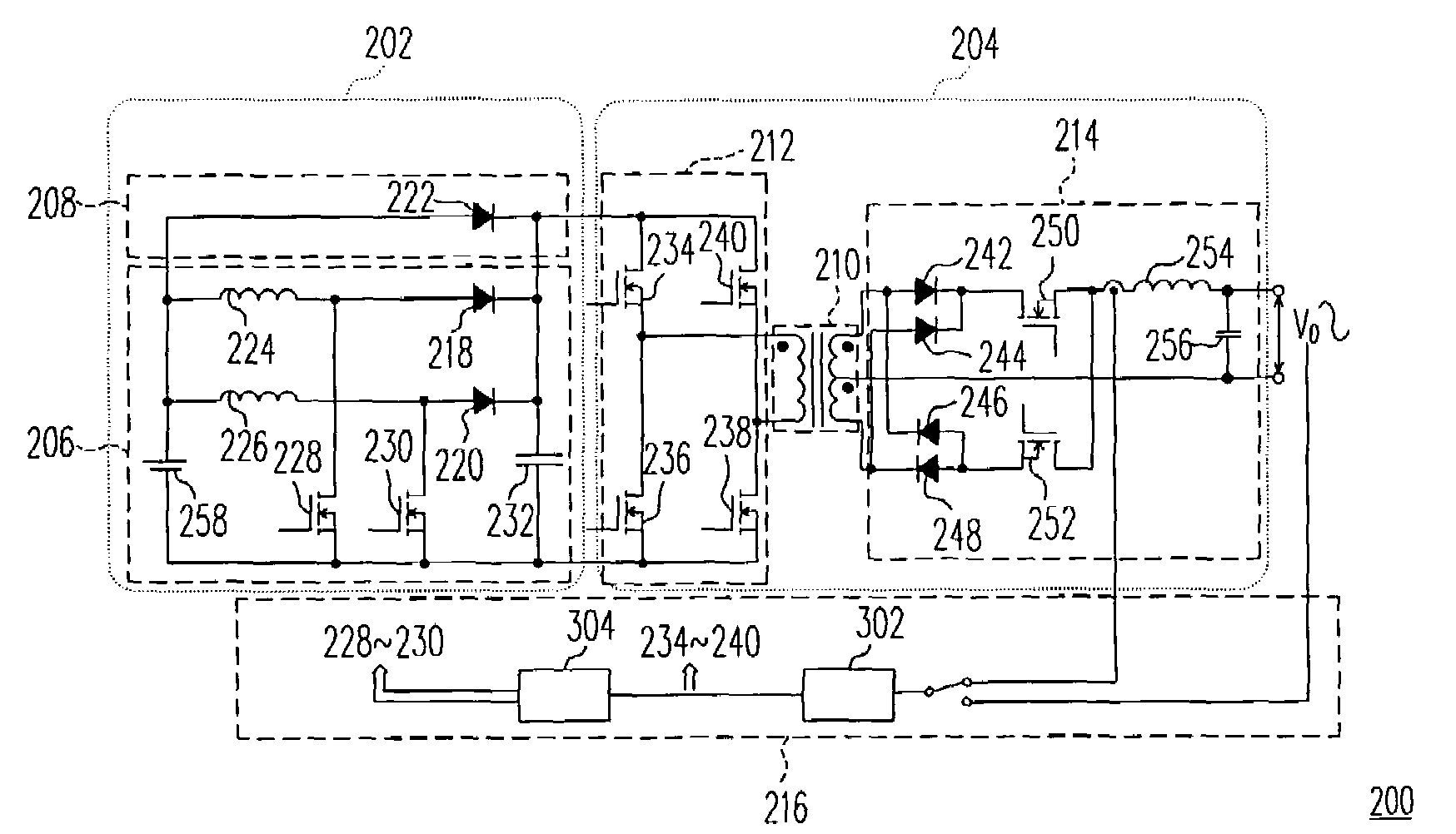
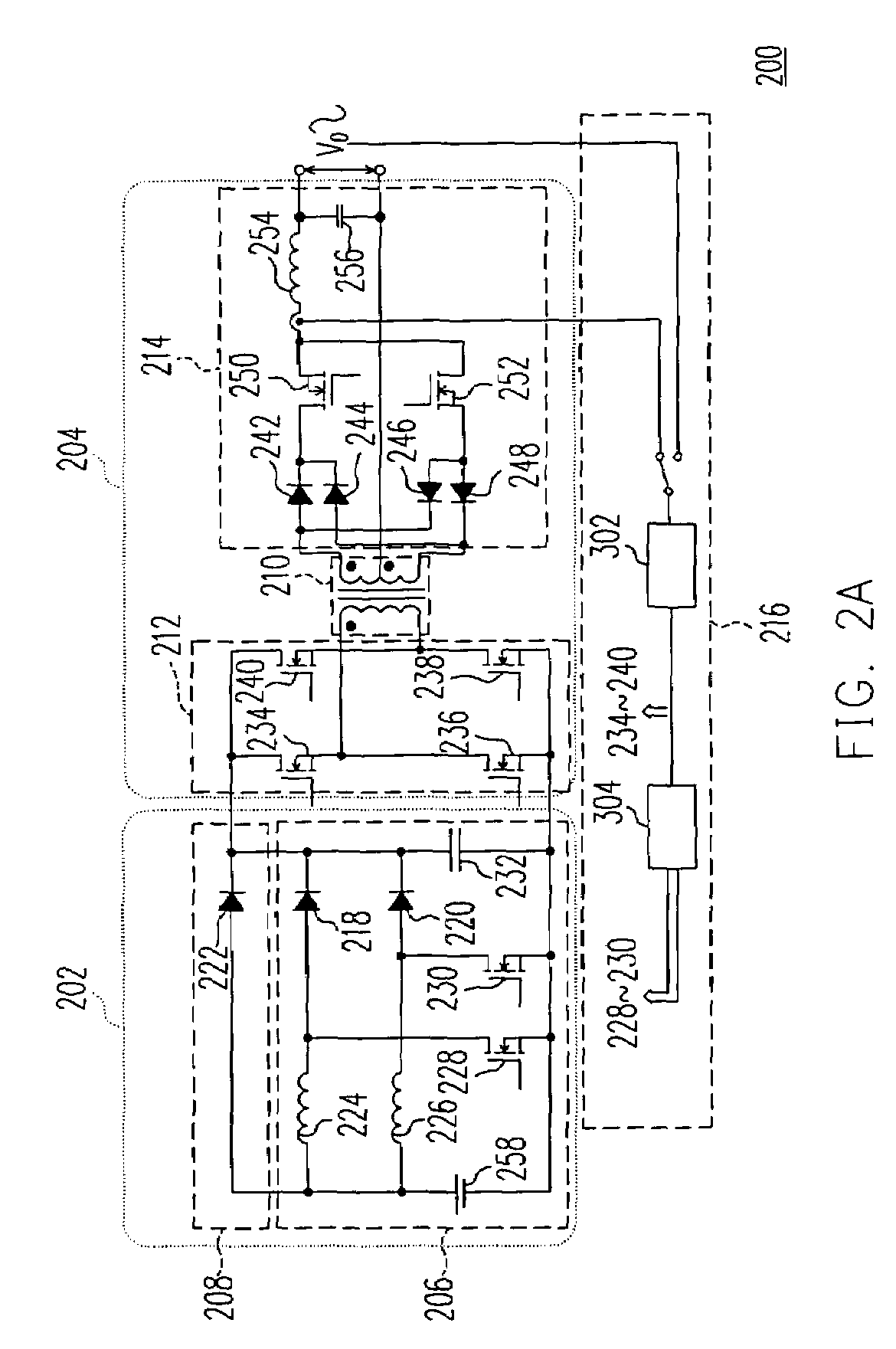
[0028]FIG. 2A is a circuit diagram of a DC-AC converter, according to an embodiment of the invention, wherein the DC-AC converter includes a voltage boost module 202, a DC-AC converting module 204 and a feedback module 216.

[0029]The voltage boost module 202 of the embodiment includes a voltage bypass circuit 208 and a voltage boost circuit 206. Here the voltage boost circuit 206, in fact, can be seen as a dual voltage boost circuit, which includes inductors 224 and 226, diodes 218 and 220, a capacitor 232, a first transistor switch 228 and a second transistor switch 230.

[0030]Wherein, one end of each of the inductors 224 and 226 is coupled with the positive end of a DC input power 258, and another end thereof is coupled with the node between diodes 218 and 220. One end of the first transistor switch 228 is coupled with the common end of the inductor 224 and the diode 218, and the other end thereof is coupled with the common end of the capacitor 232 and the DC input power 258.

[0031]T...


PUM


Abstract

A DC-AC converter is applicable for transforming direct current (DC) to alternating current (AC). The DC-AC converter includes a voltage boost module and a DC-AC converter module. Herein the voltage boost module includes a voltage bypass circuit and a voltage boost circuit, both of which receive input voltage from DC input power. Meantime, the voltage bypass circuit sends out the received input voltage, and the voltage boost circuit will operate to increase DC output voltage from the DC input as the DC output voltage from the voltage bypass circuit is not high enough to meet requirement by AC output power. The DC-AC converter module receives the output voltage from the voltage boost module and converts the received voltage to the required AC output power.

Description

CROSS-REFERENCE TO RELATED APPLICATION[0001]This application claims the priority benefit of Taiwan application serial no. 93133756, filed on Nov. 5, 2004. All disclosure of the Taiwan application is incorporated herein by reference.BACKGROUND OF THE INVENTION[0002]1. Field of Invention[0003]The present invention relates to an electric converter. More particularly, the present invention relates to a DC-AC converter.[0004]2. Description of the Prior Art[0005]A structure of DC-AC converter of the conventional art applicable to the situation with input voltage in large range is illustrated in FIG. 1, wherein the DC-AC converter 100 includes a stage-1 voltage boost circuit 102, a stage-2 DC-DC converter 104 and a stage-3 DC-AC converter 106.[0006]Therein, the stage-1 voltage boost circuit 102 is comprised by a DC input power 108, an inductor 110, a transistor switch 112, a diode 114 and a capacitor 116. The stage-1 voltage boost circuit 102 boosts its voltage to a level required by outpu...

Claims


Application Information

Patent Timeline
Patent Type & Authority Patents(United States)
IPC IPC(8): H02M7/00H02M3/335
CPCH02M3/33507H02M3/33592Y02B70/1475Y02B70/10
Inventor LEE, CHIH-CHANGLEE, LEI-MING
Owner DELTA ELECTRONICS INC
Why Eureka
Try Eureka