
Capping device with force adjustment mechanism and method of adjusting

a technology of force adjustment mechanism and cap, which is applied in the direction of caps, rotating screw stopper insertion, application, etc., can solve the problems of inability to properly fit caps on containers, and inability to adjust biasing force in a timely manner, so as to reduce the fouling of caps and downtime, prevent inadvertent adjustment of biasing force during use, and improve the consistency of axial force

Inactive Publication Date: 2008-02-19
BEVCORP
View PDF29 Cites 11 Cited by
  • Summary
  • Abstract
  • Description
  • Claims
  • Application Information

AI Technical Summary

Benefits of technology

The solution prevents unwanted adjustment of the biasing force, enhancing the consistency of axial force applied to caps, reducing cap fouling and downtime, and allowing users to accurately set each capping device to a desired force setting.

Problems solved by technology

Otherwise, the cap may not properly fit on the container.
However, the setscrew may be prone to movement during use.
The vibration to the capping device caused by rotation and upward and downward movement associated with repetitive operation may inadvertently release the setscrew from position thereby resulting in unwanted movement of the collar out from the predetermined adjustment position thereby undesirably adjusting the biasing force.

Method used


Image

  • Capping device with force adjustment mechanism and method of adjusting
  • Capping device with force adjustment mechanism and method of adjusting
  • Capping device with force adjustment mechanism and method of adjusting

Examples


Embodiment Construction

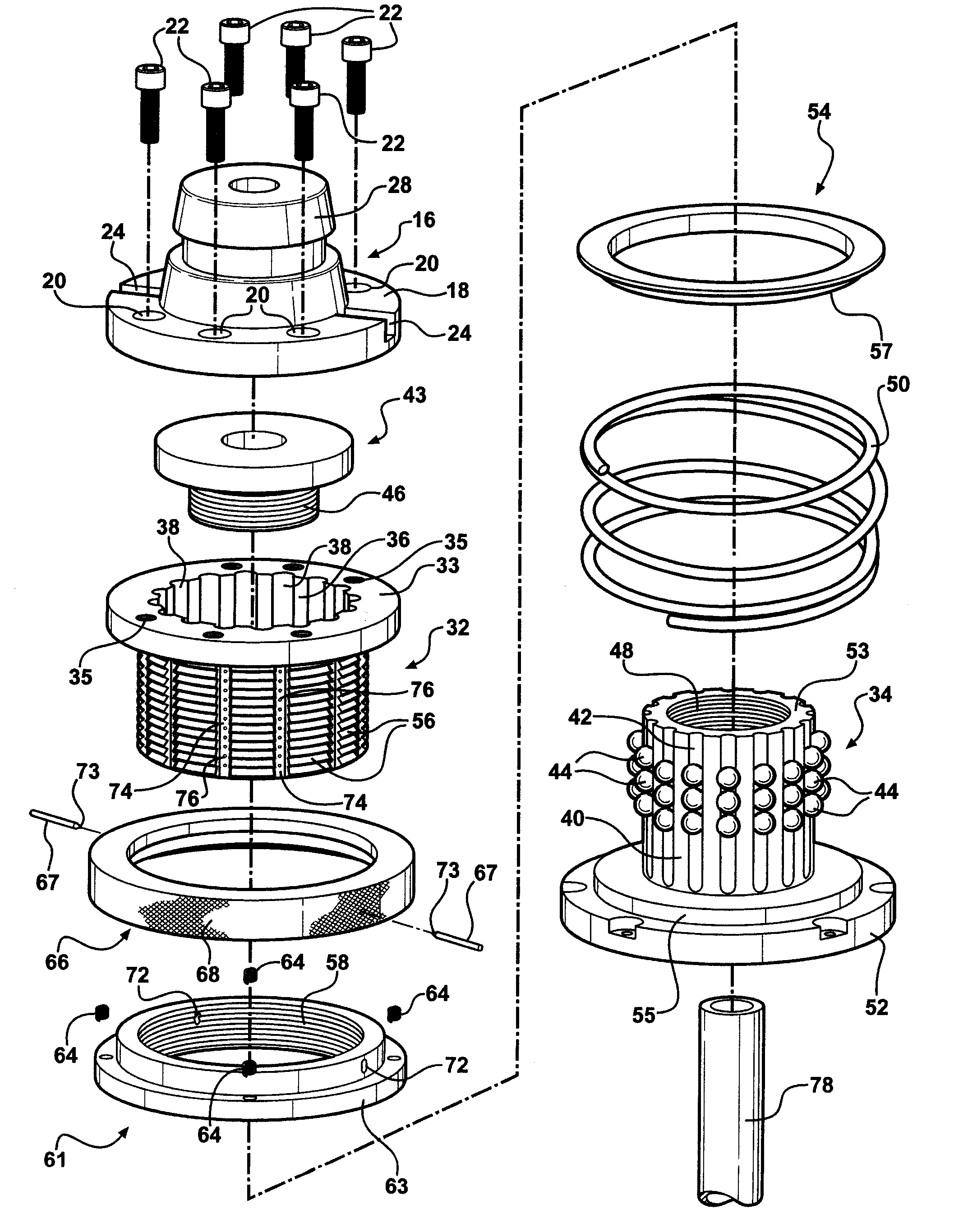
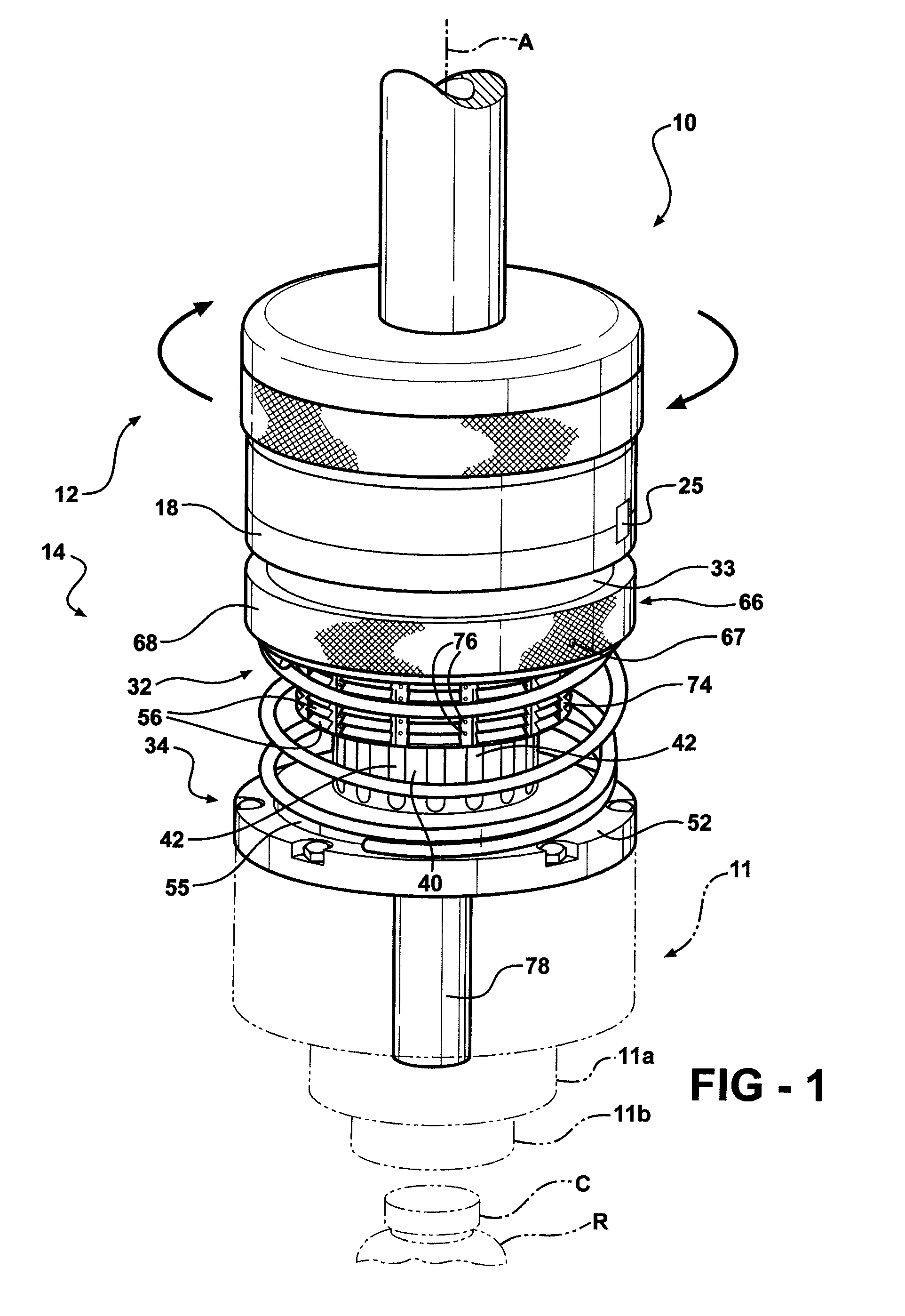
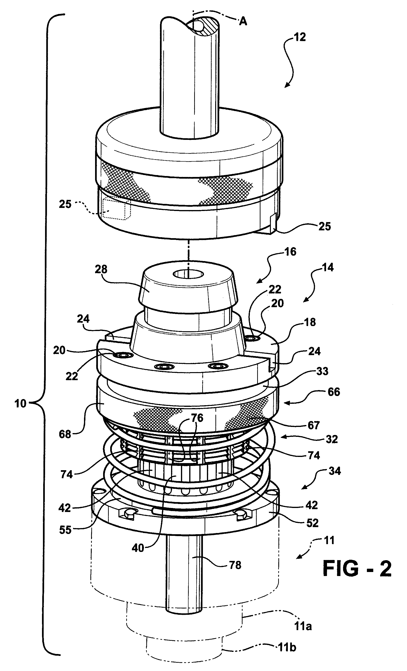
[0019]Referring to the Figures wherein like numerals indicate like or corresponding parts throughout the several views, a capping device is generally shown at 10 in FIGS. 1 and 2. The capping device 10 includes an upper portion 12 and a lower portion 14. As discussed in greater detail below, the upper portion 12 mounts to a capping machine (not shown), which imparts rotation to the capping device 10 about an operational axis A via a drive motor, turret assembly, or other drive source. The lower portion 14 has a capping unit 11 (shown in phantom) mounted at a lower end thereof. The capping unit 11 may comprise a clutch 11a and a cap-engaging portion 11b such as disclosed in U.S. Pat. No. 6,240,678, hereby incorporated by reference. The rotation of the capping device 10 ultimately provides torque to the cap-engaging portion 11b in a conventional manner to thread pre-threaded caps C onto containers R as the containers R and the caps C pass through the capping machine. The capping devic...


PUM

PropertyMeasurementUnit
axial forceaaaaaaaaaa
biasing forceaaaaaaaaaa
rotationaaaaaaaaaa

Abstract

A capping device fits caps onto containers by applying an axial force to the caps as they are threaded onto the containers. The capping device utilizes a drive member rotatable about an operational axis for imparting rotation to a capper body slidably coupled to the drive member. A helical spring urges the capper body away from the drive member with a biasing force. An adjustment mechanism adjusts the biasing force thereby adjusting the axial force applied to the caps as they are threaded onto the containers. A pair of retaining pins move between a latched position to prevent adjustment of the biasing force and an unlatched position to allow adjustment of the biasing force. The retaining pins are biased in the latched position to prevent inadvertent adjustment of the biasing force during use.

Description

RELATED APPLICATIONS[0001]This application claims the benefit of U.S. Provisional Patent Application Ser. No. 60 / 723,390, filed on Oct. 4, 2005, the advantages and disclosure of which are hereby incorporated by reference.FIELD OF THE INVENTION[0002]The present invention generally relates to a capping device for fitting caps onto containers, particularly beverage containers. More specifically, the present invention relates to the capping device having a configuration for applying an axial force to pre-threaded caps as they thread onto the containers. The capping device also includes an adjustment mechanism for adjusting the axial force to accommodate different applications and / or to optimize operation of a capping machine.BACKGROUND OF THE INVENTION[0003]Capping machines typically utilize multiple capping devices, also known as capping heads or headsets, for fitting pre-threaded caps onto containers to secure contents disposed inside the containers. A typical capping device includes ...

Claims


Application Information

Patent Timeline
Patent Type & Authority Patents(United States)
IPC IPC(8): B67B3/20
CPCB67B3/2066B67B2201/10Y10T279/17957Y10T29/53322Y10T29/49815
Inventor BROWN, MICHAEL J.
Owner BEVCORP
Learn More