Rivet monitoring system

a monitoring system and rivet technology, applied in the direction of manufacturing tools, instruments, safety devices, etc., can solve the problems of inexperienced assembly operators, complex arrangement of rivets, blind side set ends of rivets that cannot be visually inspected for correct joint completion, etc., to achieve the effect of increasing assembly speed and productivity

Active Publication Date: 2008-02-19
NEWFREY
View PDF16 Cites 30 Cited by
  • Summary
  • Abstract
  • Description
  • Claims
  • Application Information

AI Technical Summary

Problems solved by technology

One of the disadvantages of a blind rivet setting to a hollow box section is that the blind side set end of the rivet cannot be visually inspected for a correctly completed joint.
Also there could be occasions where assembly operators are inexperienced or the arrangements of rivets are complex.
Further, it is possible that rivets are incorrectly installed or perhaps not installed at all.
To inspect assemblies after completion is not only expensive and unproductive and in some instances it is virtually impossible to identify if the correct rivet has been used in a particular hole.
The current monitoring of a rivet during the setting process has been limited to the use of two methods.
This current method is limited to use in detecting fluid pressure alone.
This option used equipment which is considerably larger in size and has limited field capability as a result.

Method used


Image

  • Rivet monitoring system
  • Rivet monitoring system
  • Rivet monitoring system

Examples


Embodiment Construction

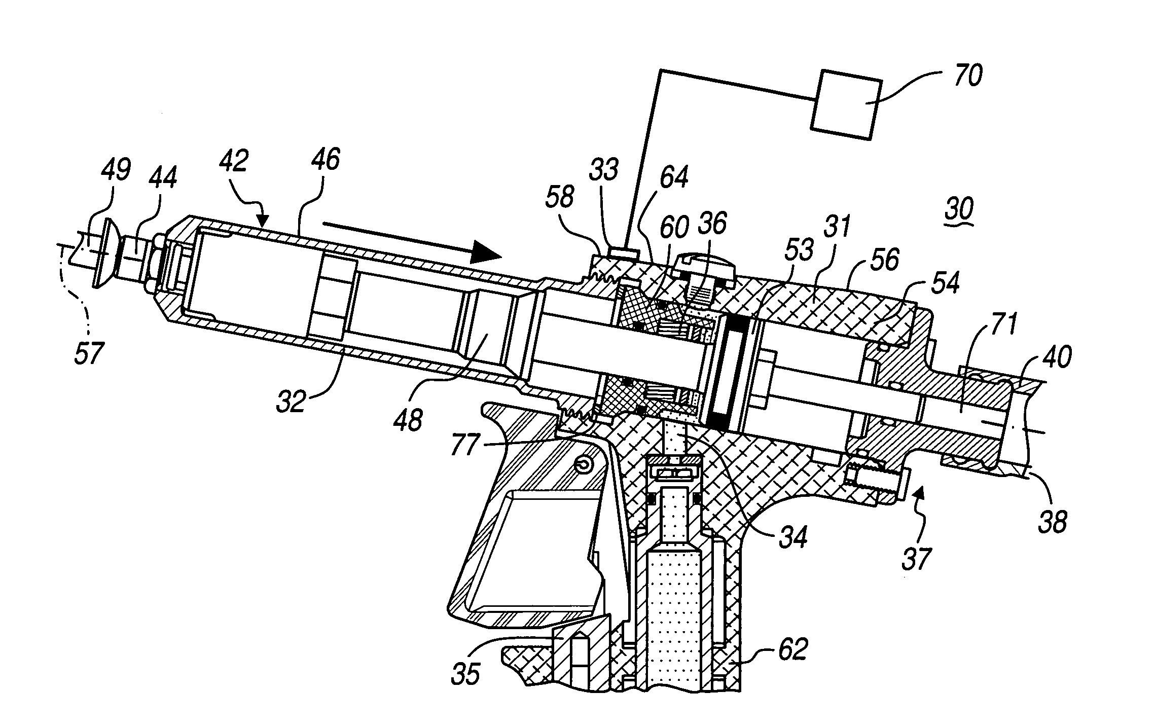
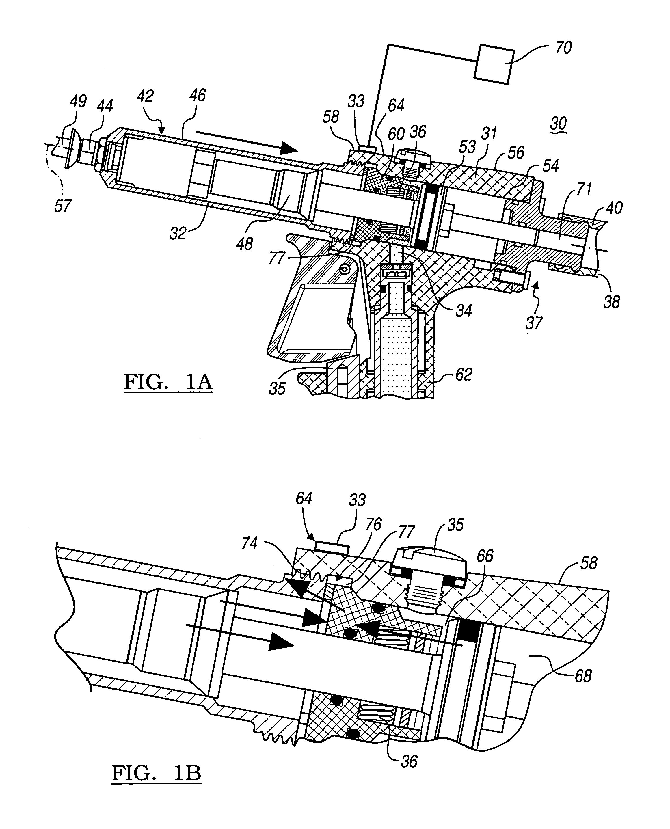
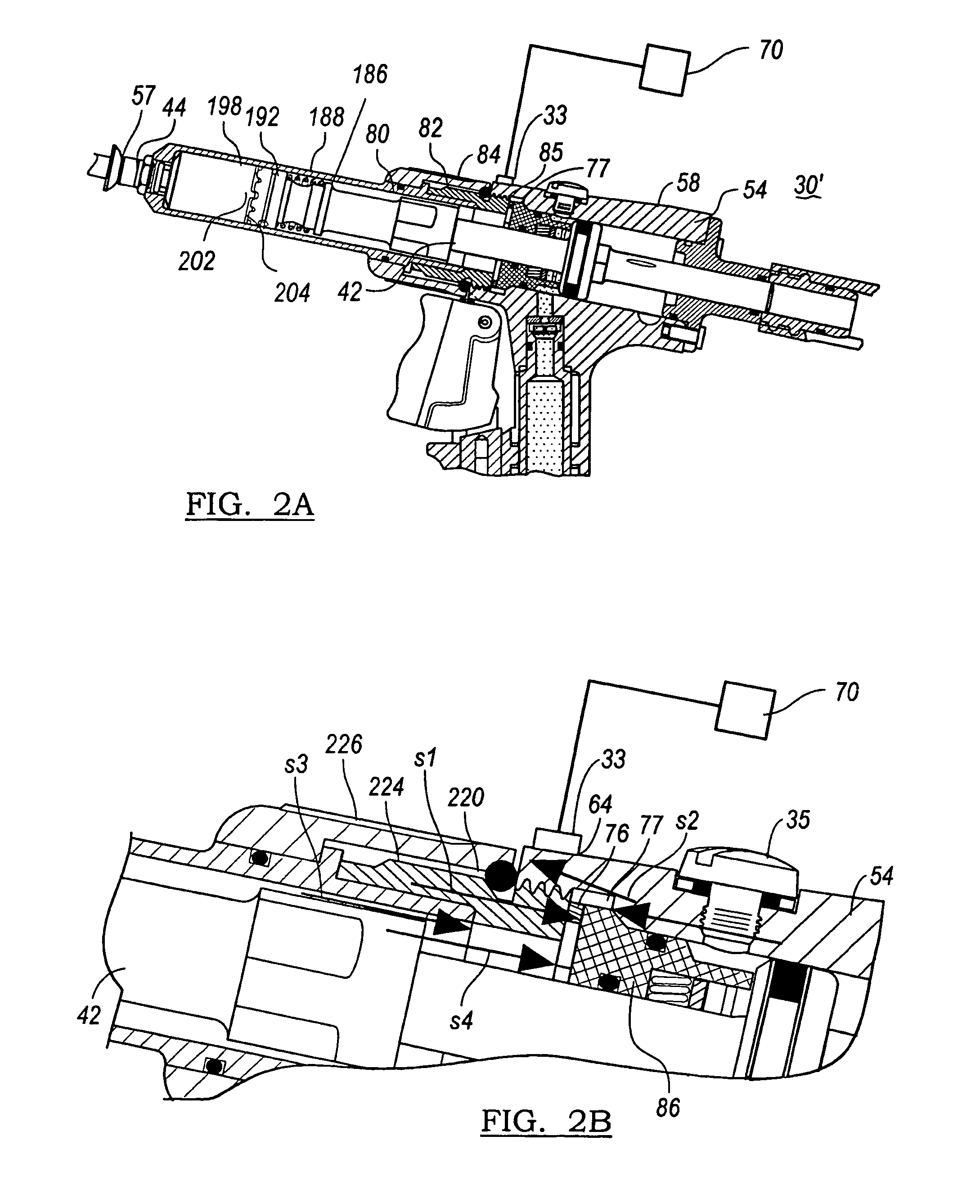
[0023]The following description of the preferred embodiments is merely exemplary in nature and is in no way intended to limit the invention, its application, or uses. The system is configured to confirm the quality of the setting process and of the resultant set. The system uses a rivet setting machine having a first member configured to apply a setting force to a fastener to set the fastener. A coupling structure is provided which is configured to apply reaction forces to the fastener in response to the setting force. A sensor is attached to the coupling structure for sensing changes in physical parameters within said coupling structure induced by the reaction forces.

[0024]The first member applies the setting force along an axis to a first side of the fastener and the setting force is resisted by a second member which applies a reaction force generally parallel to setting force. This reaction force is caused by elastic deformation in the coupling structure.

[0025]The sensor is confi...


PUM

PropertyMeasurementUnit
frequencyaaaaaaaaaa
thicknessaaaaaaaaaa
forceaaaaaaaaaa

Abstract

A rivet monitoring system is provided which has a micro-strain or micro fluid pressure sensor that measures strains or pressures within a tool component. These measured signals are compared to a number of tolerance bands formed about median strain or pressure versus time curve. Various techniques are provided to analyze the measured data with respect to the tolerance bands to determine if a particular rivet set is acceptable.

Description

CROSS-REFERENCE TO RELATED APPLICATIONS[0001]This application is a continuation of PCT International Application No. PCT / US2005 / 009461, filed Mar. 22, 2005, which claims the benefit of U.S. Provisional Applications Ser. No. 60 / 555,989 filed Mar. 24, 2004, Ser. No. 60 / 567,576 filed May 3, 2004, Ser. No. 60 / 587,971 filed Jul. 14, 2004, Ser. No. 60 / 589,149 filed Jul. 19, 2004, Ser. No. 60 / 612,772 filed Sep. 24, 2004, and Ser. No. 60 / 625,715 filed Nov. 5, 2004. The disclosures of the above applications are incorporated herein by reference.FIELD OF THE INVENTION[0002]The present invention relates to a method for detecting and monitoring a rivet setting process to determine the acceptability of the rivet being set through the use of micro-strain or pressure sensor technology for automatic, semi-automatic and manual rivet setting tools.BACKGROUND AND SUMMARY OF THE INVENTION[0003]Mechanical assemblies often use fasteners and typically blind rivets to secure one or more components together ...

Claims


Application Information

Patent Timeline
Patent Type & Authority Patents(United States)
IPC IPC(8): B21J15/28B23P11/00B21J15/02B21J15/06B21J15/10
CPCB21J15/043B21J15/10B21J15/105B21J15/28B21J15/285Y10T29/53748Y10T29/53739Y10T29/53743Y10T29/5373
Inventor CHITTY, EYMARD JTAYLOR, BRIAN MTHOMAS, PETER CVIGLIOTTI, DANIEL PWEEKS, GEOFFREY
Owner NEWFREY
Why Eureka
Try Eureka