Progressive resistance lifting mechanism for a window covering

a technology of progressive resistance and lifting mechanism, which is applied in the direction of door/window protective device, construction, building components, etc., can solve the problems of insufficient satisfaction of external cord window covering adjustment mechanism, inability to adjust the position of external cord window covering, and cords presenting safety hazards for infants and toddlers, etc., to achieve convenient positioning, reliable performance, and easy cutting to different widths

Inactive Publication Date: 2008-02-19
SHADES UNLTD
View PDF47 Cites 67 Cited by
  • Summary
  • Abstract
  • Description
  • Claims
  • Application Information

AI Technical Summary

Benefits of technology

[0010]This invention provides a lifting mechanism for a window covering which facilitates a cordless window covering to be easily positioned as desired and easily repositioned, by merely placing a bottom rail of the window covering where the user desires it to be. The window covering includes a top rail and a bottom rail with a window covering suspended therebetween. At least one cord, and typically two cords extend between the top rail and the bottom rail. A cord collector is located within one of the rails with the cord coupled to the cord collector at the end of the cord adjacent the cord collector. The cord collector is coupled to a biaser which biases the cord collector in a direction encouraging the cord collector to collect the cord thereon. The cord is routed so that the weight of the shade counteracts the forces exerted by the biaser so that the cord remains stationary and hence the bottom rail of the window covering remains stationary, unless external forces are applied to the system.
[0011]Additionally, a progressive resister is coupled to the cord collector. The progressive resister adds a progressive amount of resistance to motion of the cord collector as a greater amount of cord is taken away from the cord collector. Thus, when the bottom rail is most distant from the top rail and the cord is mostly off of the cord collector, the progressive resister exerts a maximum resistance force against collection of the cord by the cord collector, in effect resisting the action of the biaser upon the cord collector. When the bottom rail is closer to the top rail and a greater amount of the cord is collected with the cord collector, a relatively lesser amount of resistance is exerted upon the cord collector by the progressive resister, so that action of the biaser upon the cord collector is opposed to a lesser extent. The action of the progressive resister allows the window covering to avoid the “bounce” phenomena associated with the biaser, such as a spring, exerting an excessive force upon the cord collector when the cord is a maximum amount away from the cord collector. The amount of resistance added by the progressive resister is thus correlated with the amount of cord collected with the cord collector and by correlation, the position of the bottom rail relative to the top rail.

Problems solved by technology

Such external cord based window covering adjustment mechanisms are less than entirely satisfactory.
The cords can become entangled with themselves or other structures, rendering the cords non-functional in adjusting the position of the window covering.
The cords present a safety risk for infants and toddlers.
Also, the locking mechanisms for locking the cord in the desired position so that the window covering bottom rail is positioned where desired is often difficult to use effectively and is prone to wearing out, so that the window covering is effectively stalled in either the fully open or fully closed position.
While such balanced cordless shades are taught in the prior art, such balanced cordless shades have heretofore required complex mechanisms which have exhibited various undesirable performance characteristics.
As the bottom rail moves downward, the strength of the spring increases, making it difficult to cause the bottom rail to remain fixed in the lower position.
When a weaker spring or other biaser is used, it has insufficient force to keep the bottom rail from falling down at least somewhat when the user desires that the window covering be entirely open.

Method used


Image

  • Progressive resistance lifting mechanism for a window covering
  • Progressive resistance lifting mechanism for a window covering
  • Progressive resistance lifting mechanism for a window covering

Examples


Embodiment Construction

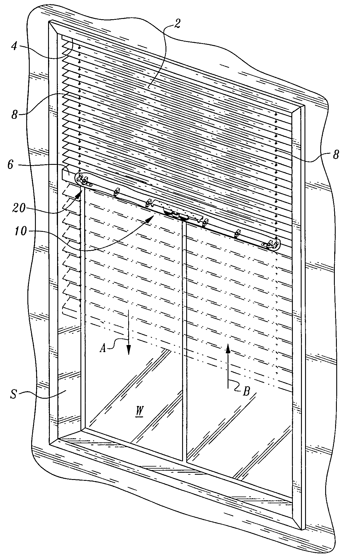
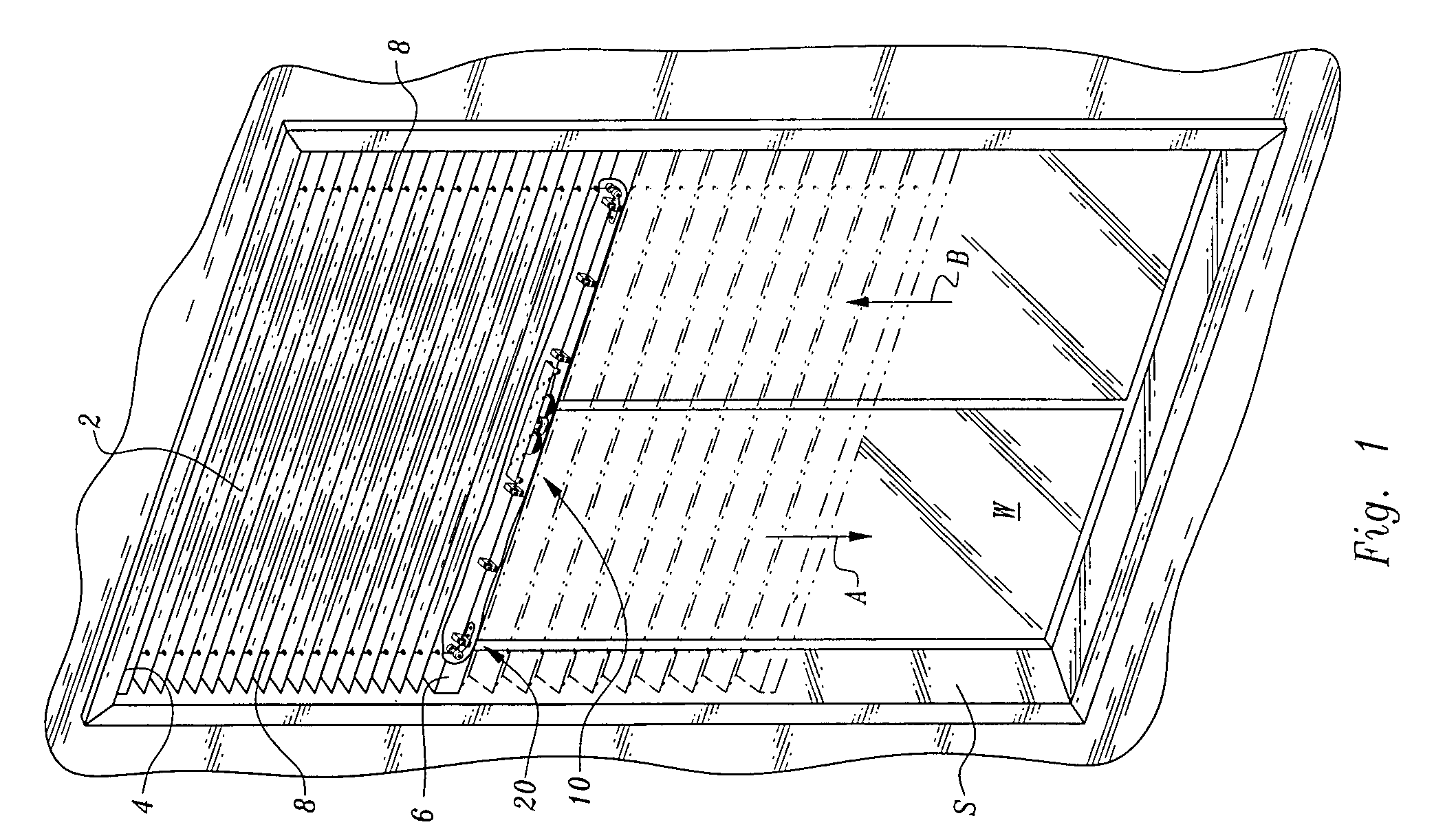
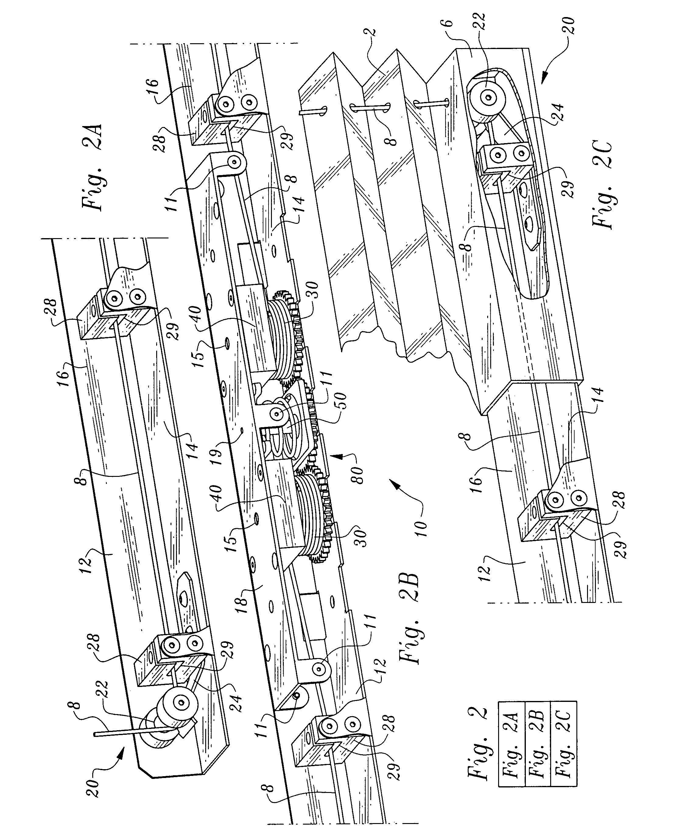
[0038]Referring to the drawings, wherein like reference numerals represent like parts throughout the various drawing figures, reference numeral 10 (FIGS. 1 and 6) is directed to a lifting mechanism for a window covering 2. The window covering 2 generally includes a top rail 4 parallel with and spaced from a bottom rail 6 with the window covering 2 structure extending between the top rail 4 and bottom rail 6. Cords 8 extend between the top rail 4 and the bottom rail 6. The lifting mechanism 10 acts upon the cords 8 within one of the rails 4, 6 so that the bottom rail 6 can maintain equilibrium wherever the bottom rail 6 is positioned by a user. In this way, a user can raise the bottom rail 6 (arrow B) or lower the bottom rail 6 (arrow A) to occlude the window W or expose the window W, with the bottom rail 6 conveniently remaining where it is left by the user.

[0039]In essence, and with particular reference to FIGS. 1, 3 and 6, basic details of the lifting mechanism 10 are described. T...


PUM


Abstract

A lifting mechanism is provided for a window covering which allows a bottom rail of the window covering to maintain a static position unless raised or lowered by a user. The lifting mechanism is included within either a top or bottom rail of the window covering. The lifting mechanism includes cords which pass from a rail including the lifting mechanism to a rail not including the lifting mechanism and about cord redirectors located within the rail including the lifting mechanism. The lifting mechanism includes spools and associated springs for gathering excess portions of the cord thereon. A progressive resister is coupled to the spools with the progressive resister providing different amounts of resistance to spool rotation depending on the amount of cord upon each spool.

Description

FIELD OF THE INVENTION[0001]The following invention relates to lifting mechanisms for window coverings of various varieties. More particularly, this invention relates to lifting mechanisms for window coverings which automatically provide sufficient lifting force so that a bottom rail of the window covering will remain in a position where it is placed by a user until the bottom rail is again moved by a user to a new position, without requiring engaging or releasing of locking mechanisms through buttons, cords or other manually actuated locking mechanisms.BACKGROUND OF THE INVENTION[0002]Window coverings are provided in a wide variety of styles and configurations to both provide the function of at least partially occluding the passage of light through a window and enhancing an appearance of a room in which the window is located. Such window coverings can include shades which are typically continuous from a top rail at an upper end of the window to a bottom rail at a bottom end of the ...

Claims


Application Information

Patent Timeline
Patent Type & Authority Patents(United States)
IPC IPC(8): E06B9/30
CPCE06B9/322E06B2009/3222
Inventor MILITELLO, DAVID R.SHEVICK, BARRY L.LATHROP, III, ROBERT L.DENDULK, BRUCE R.
Owner SHADES UNLTD
Why Eureka
Try Eureka