
Specimen-container rack for automated clinical instrument

a technology for automated clinical instruments and specimen containers, which is applied in the field of specimen container racks, can solve the problems of not being well suited to use with a magnetic transport system adapted to the transport rack, and the specimen container rack described above is useful in a unidirectional magnetic transport system

Active Publication Date: 2008-02-19
BECKMAN COULTER INC
View PDF16 Cites 31 Cited by
  • Summary
  • Abstract
  • Description
  • Claims
  • Application Information

AI Technical Summary

Benefits of technology

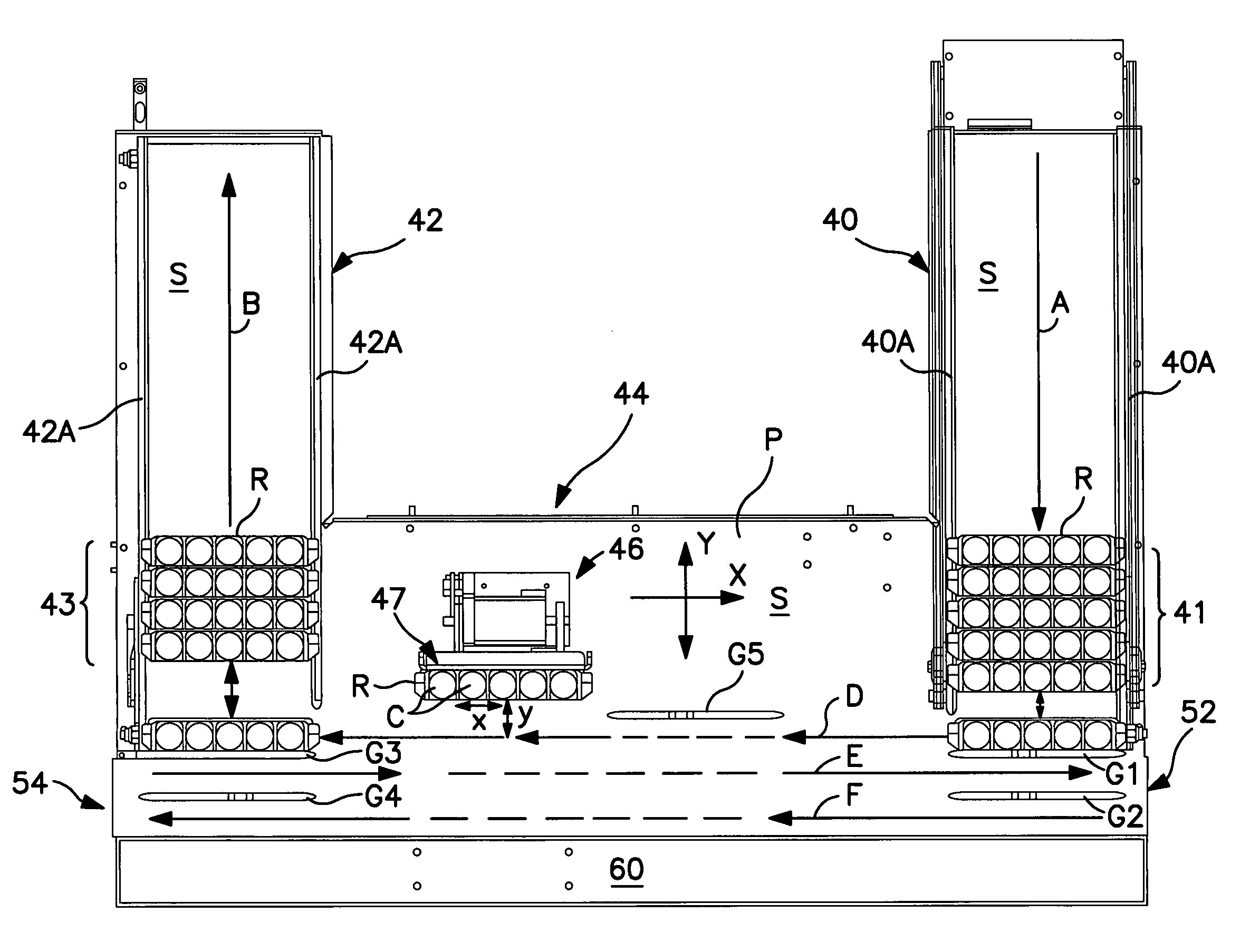
The invention is a specimen-container rack that can be easily transported by a magnetic transport system in mutually-perpendicular directions on a non-magnetic plate within a specimen-transport apparatus. The rack can also be transported by two different independent transport systems and can be releasably engaged by a specimen-mixing mechanism that operates to repeatedly invert the rack for effecting specimen-mixing. The rack has structure that allows it to be magnetically transported over a supporting surface in mutually-perpendicular directions, making it more versatile in its application than previous racks designed for linear movement in only one direction.

Problems solved by technology

The specimen-container rack described above, while useful in a unidirectional magnetic transport system, is not well suited for use with a magnetic transport system adapted to transport racks in mutually perpendicular directions, i.e., in an X / Y plane.

Method used


Image

  • Specimen-container rack for automated clinical instrument
  • Specimen-container rack for automated clinical instrument
  • Specimen-container rack for automated clinical instrument

Examples


Embodiment Construction

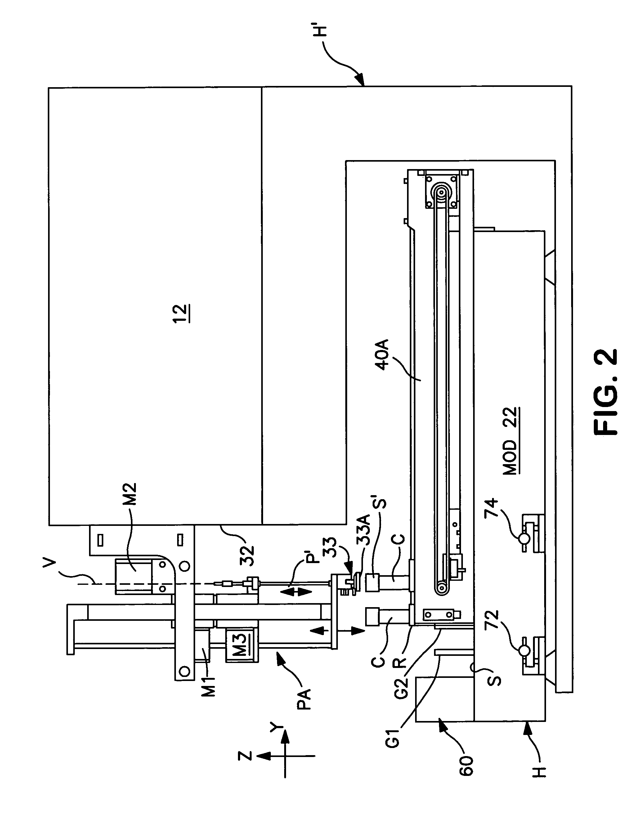
[0035]The specimen-container rack of the invention is especially useful with a stand-alone specimen-transport module of the type described in the above-referenced U.S. application Ser. No. 10 / 794,702 filed Mar 5, 2004 entitled “Specimen-Transport Module for a Multi-Instrument Clinical Workcell.” It will be appreciated, however, that the invention is also useful in stand-alone clinical instruments in which the specimen-transport system is an integral part of the instrument, rather than an accessory to the instrument.

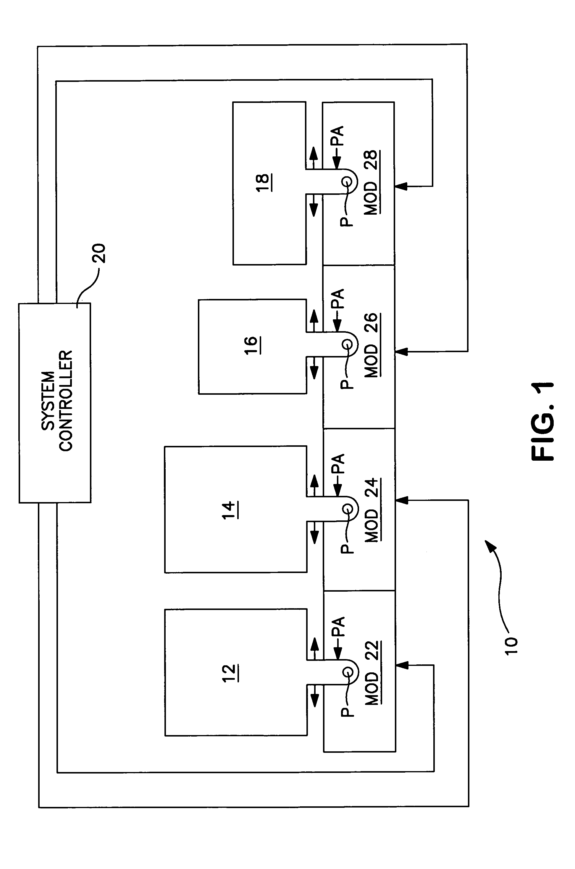
[0036]Referring now to the drawings, FIG. 1 schematically illustrates a multi-instrument workcell 10 that is adapted to analyze and / or otherwise process a whole blood specimen presented to it. Each of such specimens is contained by a test tube or other container C that is supported, together with additional containers, in a generally upright orientation and in a linear array, by a specimen-container rack R (shown and described in detail below with reference to in FIGS. 10...


PUM


Abstract

A magnetically-attractive specimen-container rack for use with a magnetic transport system for transporting racks of specimen-containers to or within an automated clinical instrument for analysis and / or processing. The specimen-container rack comprises a pair of U-shaped magnetically-attractive members mounted in the base section of the rack housing so that the distal ends of such members extend towards the base of the rack and terminate in a plane slightly short of the plane in which the rack is supported for movement atop a rack-supporting surface. Such members are adapted to cooperate with similarly-shaped permanent magnets carried by an X / Y-movable truck that underlies a non-magnetic rack-supporting plate. Other features of the rack include a pair of side-pockets formed in one side of the rack in the vicinity of the end walls of the rack housing, such pockets serving to receive a movably-mounted member associated with a linear drive mechanism by which the rack can be physically advanced edgewise along a linear path; and notch structure by which the rack can be releasably engaged by a movably-mounted plate which serves to lift and invert the rack to effect mixing of contained specimens.

Description

CROSS-REFERENCE TO RELATED APPLICATIONS[0001]Reference is made to the following patent applications filed concurrently herewith:[0002]U.S. application Ser. No. 10 / 794,702 filed Mar. 5, 2004 entitled “Specimen-Transport Module for a Multi-Instrument Clinical Workcell”, and[0003]U.S. application Ser. No. 10 / 794,686, now U.S. Pat. No. 7,028,831 issued Apr. 18, 2006 entitled “Magnetic Specimen-Transport System for Automated Clinical Instrument.”BACKGROUND OF THE INVENTION[0004]1. Field of the Invention[0005]The present invention relates to improvements in specimen-container racks of the type used to support multiple containers, e.g., test tubes, of liquid specimens for analysis or processing by a clinical instrument. More particularly, it relates to improvements in specimen-container racks of the type that are adapted to be transported over a rack-supporting surface via magnetic forces.[0006]2. The Prior Art[0007]It is known in the art to perform diagnostic tests on various liquid biolo...

Claims


Application Information

Patent Timeline
Patent Type & Authority Patents(United States)
IPC IPC(8): A47B73/00
CPCG01N35/04B01L9/06G01N2035/0415G01N2035/0477
Inventor VEINER, CRAIG R.TAPPEN, FRANK M.DEL VALLE, ROBERTOMARQUIS, RICHARD A.
Owner BECKMAN COULTER INC
Learn More