Child resistant container and cap

a container and cap technology, applied in the field of push-to-turn containers and caps, can solve the problems of requiring strength to push down and release the locking mechanism, and it is difficult for seniors to use containers and caps with this type of locking mechanism, so as to reduce the force used to unlock the cap of a container, the effect of easy manufacturing

Inactive Publication Date: 2008-02-19
REXAM PRESCRIPTION PROD INC
View PDF30 Cites 33 Cited by
  • Summary
  • Abstract
  • Description
  • Claims
  • Application Information

AI Technical Summary

Benefits of technology

[0006]The present invention reduces the force used to unlock the cap of a container and provides an easily manufactured, unitary cap, and a unitary container. In one embodiment this is achieved by molding the cap, and molding the container, so there are resilient tabs below the trailing end of the container threads and spaced around the periphery of the opening to the container, and then placing a locking member on the cap which goes between the container threads and resilient tab to lock against the trailing end of the container threads. Pushing the cap threads against the resilient tabs allows the locking member to be disengaged when the cap is turned. The tabs can be adjusted to vary the force required to disengage the lock and remove the cap.

Problems solved by technology

These squeeze-and-lock mechanisms require strong fingers and good coordination between the squeezing and turning, either of which makes it difficult for seniors to use caps with this type of locking mechanism.
Each of those also makes it difficult for seniors to use containers and caps with this type of locking mechanism.
But they do require strength to push down and release the locking mechanism.
These prior art locking containers and caps are also complex and / or costly to make.
The caps were often made of two pieces snapped together or bonded together, or the mating parts of the container and cap required complex molding or expensive after-molding-assembly.

Method used


Image

  • Child resistant container and cap
  • Child resistant container and cap
  • Child resistant container and cap

Examples


Embodiment Construction

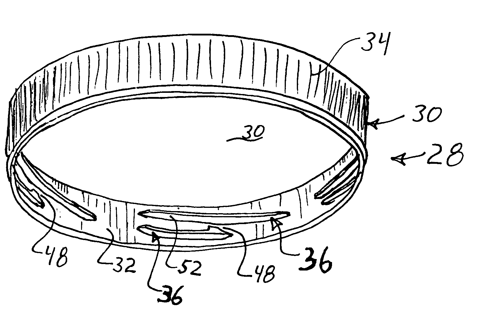
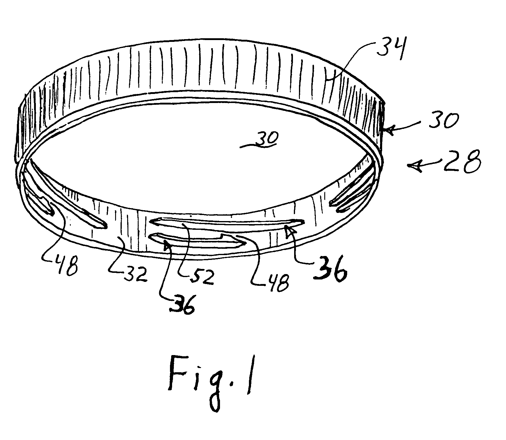
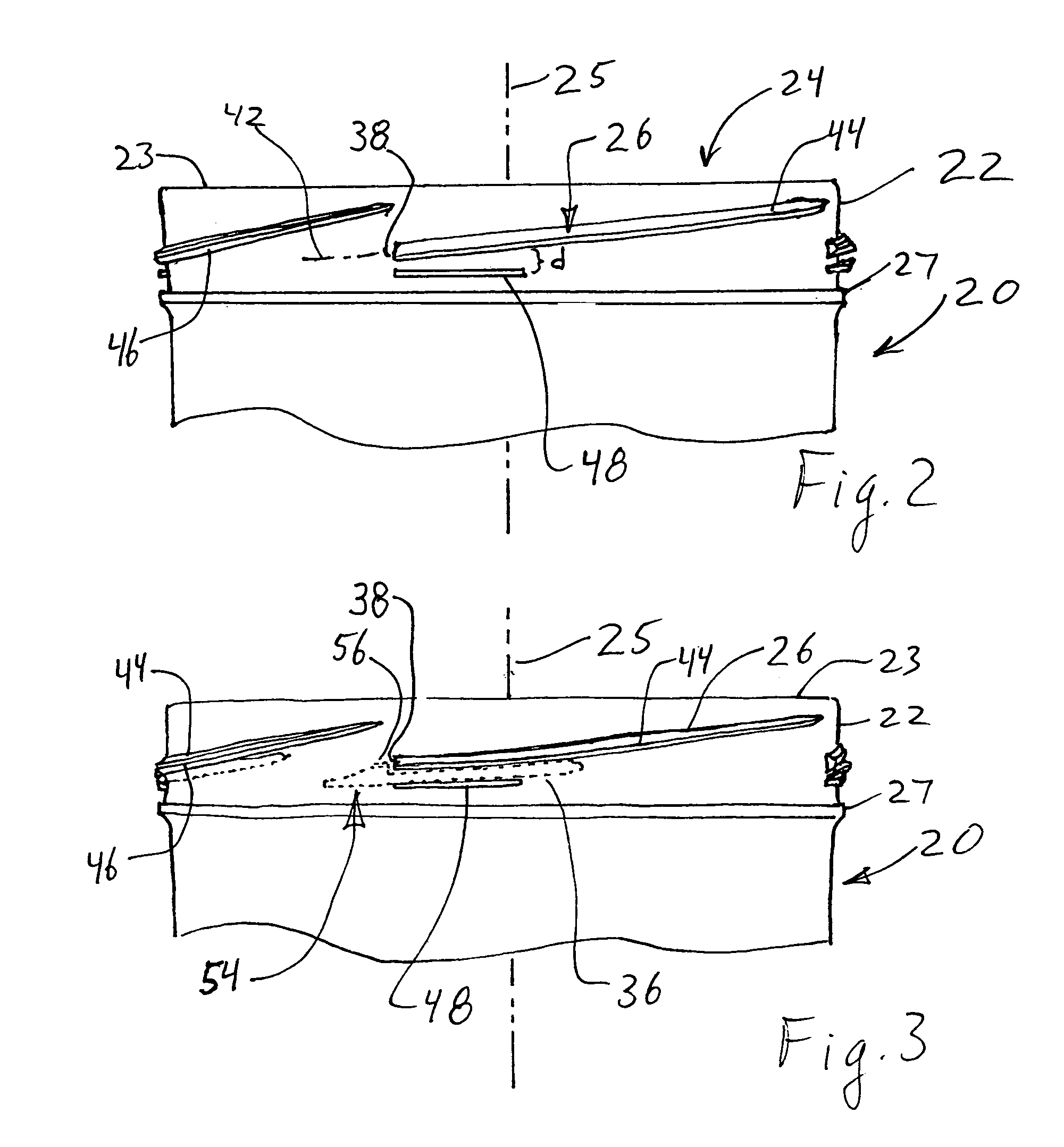
[0043]Referring to FIGS. 2-4, a container 20 has a neck 22 defining an opening 24 to the inside of the container. The neck 22 and opening 24 are typically cylindrical and centered about longitudinal axis 25 of the container 20. The neck 22 may be an identifiable portion of different thickness than the body of the container 20 as shown in FIGS. 2-3, or it may be of the same thickness as the body and simply reflect the portion of the container adjacent the opening 24 that is threaded or bears the locking components as in later embodiments of the container 20. One or more container threads 26 are formed on the neck 22 and typically extend along a helix concentric with the longitudinal axis 25. The threads 26 can be internal or external, but are preferably external threads. The depicted container 20 has a flange 27 around its exterior circumference against which the lower edge of the cap 28 abuts, but the flange is optional.

[0044]Referring additionally to FIGS. 1 and 5, a cap 28 is size...


PUM


Abstract

A locking cap and container is provided for a container having an opening surrounded by a neck with container threads thereon that are sized and located to threadingly engage cap threads formed on a skirt of the cap. A shaped distal end is formed on a distal end of the container threads and a barb is formed on the distal end of the cap threads. A resilient locking tab extends from the container, and is located below the shaped distal end and spaced apart from the shaped distal end a distance sufficient to allow passage of the barb beyond the shaped distal end but sufficiently close to resiliently urge the barb into overlapping rotational alignment with the shaped end. The shaped end is configured to lockingly engage the barb when the tab holds them in alignment. Pushing down on the cap pushes the thread against the locking tab and allows disengagement of the barb from the shaped distal end and movement of the barb past the shaped distal end to unlock the cap.

Description

FIELD OF INVENTION[0001]This invention relates to push-and-turn containers and caps that are difficult for children to remove but easy for adults and the elderly to remove.BACKGROUND OF THE INVENTION[0002]A number of locking mechanisms are used to deter children from gaining access to the contents of containers, such as pharmaceuticals, chemicals, and other items that could be harmful or undesirable for children to consume or ingest. But the locking mechanism must still allow adults and the elderly to open the containers. One type of locking mechanism uses a cap which a person must squeeze to release the lock, and then turn the cap on the container while still squeezing. These squeeze-and-lock mechanisms require strong fingers and good coordination between the squeezing and turning, either of which makes it difficult for seniors to use caps with this type of locking mechanism.[0003]Some containers use a locking mechanism that requires the user to visually align arrows or other indic...

Claims


Application Information

Patent Timeline
Patent Type & Authority Patents(United States)
IPC IPC(8): B65D41/06B65D41/04
CPCB65D41/0471B65D41/06
Inventor OH, JACK S.
Owner REXAM PRESCRIPTION PROD INC
Why Eureka
Try Eureka