Tool for dispensing plastic fasteners

a technology for fasteners and tools, applied in the field of fastening, can solve the problems of inconvenient use of tools, injury to both people, physical and mental strain, etc., and achieve the effect of convenient use and inexpensive manufacturing

Active Publication Date: 2008-02-19
AVERY DENNISON CORP
View PDF15 Cites 23 Cited by
  • Summary
  • Abstract
  • Description
  • Claims
  • Application Information

AI Technical Summary

Benefits of technology

[0016]It is yet another object of the present invention to provide a tool as described above which has a smooth trigger stroke.
[0017]It is yet still another object of the present invention to provide a tool as described above which is reliable.
[0018]It is yet a further object of the present invention to provide a tool as described above which has a limited number of parts, which is easy to use and which is inexpensive to manufacture.

Problems solved by technology

One such shortcoming is that no suitable tool exists for dispensing such pins into an article of clothing; consequently, the pins must be inserted manually.
As can readily be appreciated, the repeated insertion of such pins into articles of clothing, over time, can become both physically and mentally taxing.
Another shortcoming associated with the use of straight metal pins is that the pins, as noted above, have sharp ends, which can cause injury both to the person who must insert the pin into the article and to the person (i.e., consumer) who must remove the pin from the article.
Still another shortcoming associated with the use of straight metal pins is that such pins, when inserted, may cause damage to the article, either by snagging and tearing the article or by creating a conspicuous insertion hole in the article.
Still yet another shortcoming associated with the use of straight metal pins is that such pins, once inserted into an article of clothing, can be difficult to access and manipulate in such a way as to enable their removal.
Although well-known in commerce, the tool of the aforementioned '285 patent suffers from a couple notable drawbacks.
As a first drawback, the tool is not adapted to dispense fasteners from the first type of fastener clip (i.e., a clip comprising plurality of fasteners which are attached to a common runner bar).
Rather, the tool is limited to dispensing plastic fasteners from a fastener clip which does not include a common runner bar.
As a second drawback, the process of coupling and decoupling the needle carrier to and from the ejector rod carrier during the process of dispensing an individual fastener serves to roughen the trigger stroke of the tool.
As a third drawback, the process of coupling and decoupling the needle carrier to and from the ejector rod carrier during each trigger stroke is mechanically complex in nature, thereby rendering the tool more unreliable over time.

Method used


Image

  • Tool for dispensing plastic fasteners
  • Tool for dispensing plastic fasteners
  • Tool for dispensing plastic fasteners

Examples


Embodiment Construction

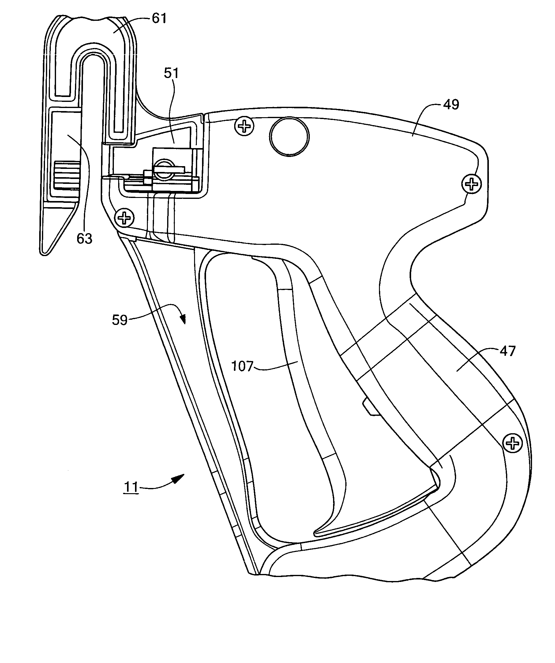
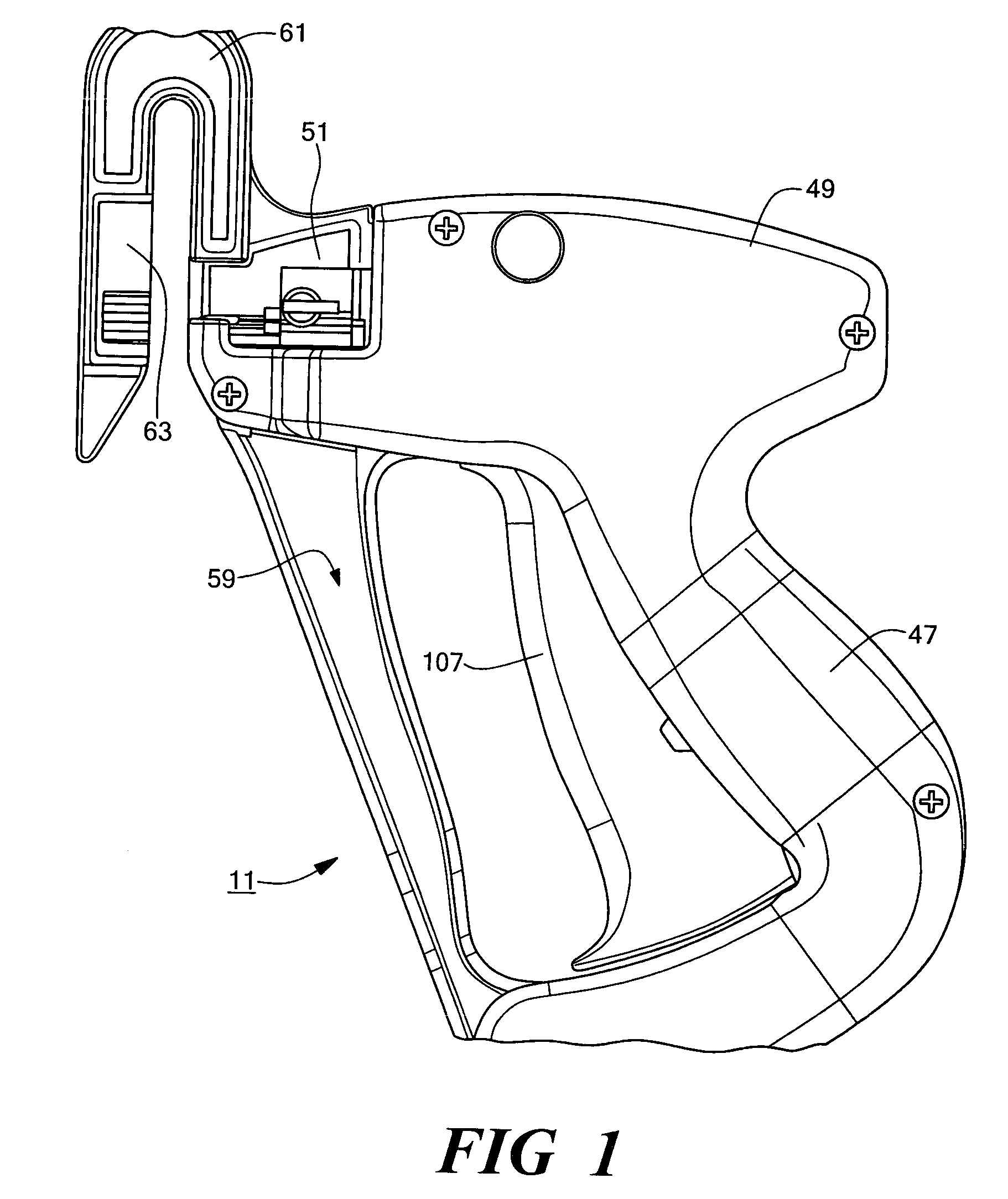
[0052]Referring now to FIG. 1, there is shown a tool for dispensing individual plastic fasteners from a fastener clip, the tool being constructed according to the teachings of the present invention and identified generally by reference numeral 11. As will be described further in detail below, tool 11 is designed principally for use in shirt-pining applications (i.e., dispensing individual plastic fasteners through a shirt so as to retain the shirt in a folded condition).

[0053]Tool 11 is designed for use in dispensing individual plastic fasteners from a fastener clip of the type which includes a common runner bar. Referring now to FIGS. 7-10, there is shown one type of fastener clip 13 which can used in conjunction with tool 11. Fastener clip 13, which is a unitary structure preferably made by molding, comprises a plurality of individual fasteners 15, fasteners 15 being arranged in a parallel, side-by-side, spaced orientation.

[0054]As seen most clearly in FIGS. 11(a) through 11(c), e...


PUM


Abstract

A tool for dispensing fasteners from a fastener clip having a runner bar comprises a housing shaped to include a handle portion, a barrel portion and a guide channel for receiving the used portion of the runner bar. A trigger assembly is pivotally mounted in the handle portion. The tool also includes a needle slide slidably mounted in the barrel portion, a needle coupled to the needle slide, and a needle slide link coupling the needle slide to the trigger assembly. An ejector slide is slidably mounted within the needle slide and adapted to receive an ejector rod which is insertable back and forth through the hollow needle. The needle slide and the ejector slide are independently coupled to the trigger assembly. An anvil extends out in front of the barrel portion and is adapted to receive a removable brush, the needle being aligned to selectively project into the brush.

Description

CROSS-REFERENCE TO RELATED APPLICATIONS[0001]The present application claims the benefit under 35 U.S.C. § 119(e) of U.S. Provisional Patent Application Ser. No. 60 / 334,026, filed Nov. 27, 2001.BACKGROUND OF THE INVENTION[0002]The present invention relates generally to the fastening of objects using plastic fasteners and relates more particularly to a novel tool for dispensing plastic fasteners.[0003]Certain articles of clothing, most notably men's dress shirts, are often packaged and sold in a folded condition so as to minimize any wrinkling of the article and so as to present the article in an otherwise flattering manner. Typically, the article is maintained in a folded condition by means of one or more straight metal pins, each of said straight metal pins typically comprising an elongated shaft terminating at one end in a sharp tip designed to penetrate the article and at the other end in a rounded head designed not to penetrate the article. Typically in use, the article is folded...

Claims


Application Information

Patent Timeline
Patent Type & Authority Patents(United States)
IPC IPC(8): B65C5/06B65C7/00
CPCB65C7/005B65C5/06
Inventor COOPER, WILLIAM J.RAYMOND, JEFFREY A.
Owner AVERY DENNISON CORP
Why Eureka
Try Eureka