Monostable shifting device with P position

a shifting device and monostable technology, applied in the direction of mechanical control devices, cycle equipment, instruments, etc., can solve the problems of misunderstanding, inability to transmit false information on the current shift position to the driver,

Inactive Publication Date: 2008-02-26
ZF FRIEDRICHSHAFEN AG
View PDF11 Cites 29 Cited by
  • Summary
  • Abstract
  • Description
  • Claims
  • Application Information

AI Technical Summary

Benefits of technology

[0008]The object of the present invention is therefore to provide a shifting device for the powerless transmission of shift commands, which makes it possible to combine the advantages of a shifting device that is stable in a plurality of shift positions with those of a monostable shifting device, so that, ...

Problems solved by technology

Monostable shifting devices have no haptic feedback on the current position of the transmission, so that it is also impossible to transmit false information on the current shift position to the driver.
A direct haptic feedback ...

Method used


Image

  • Monostable shifting device with P position
  • Monostable shifting device with P position
  • Monostable shifting device with P position

Examples


Embodiment Construction

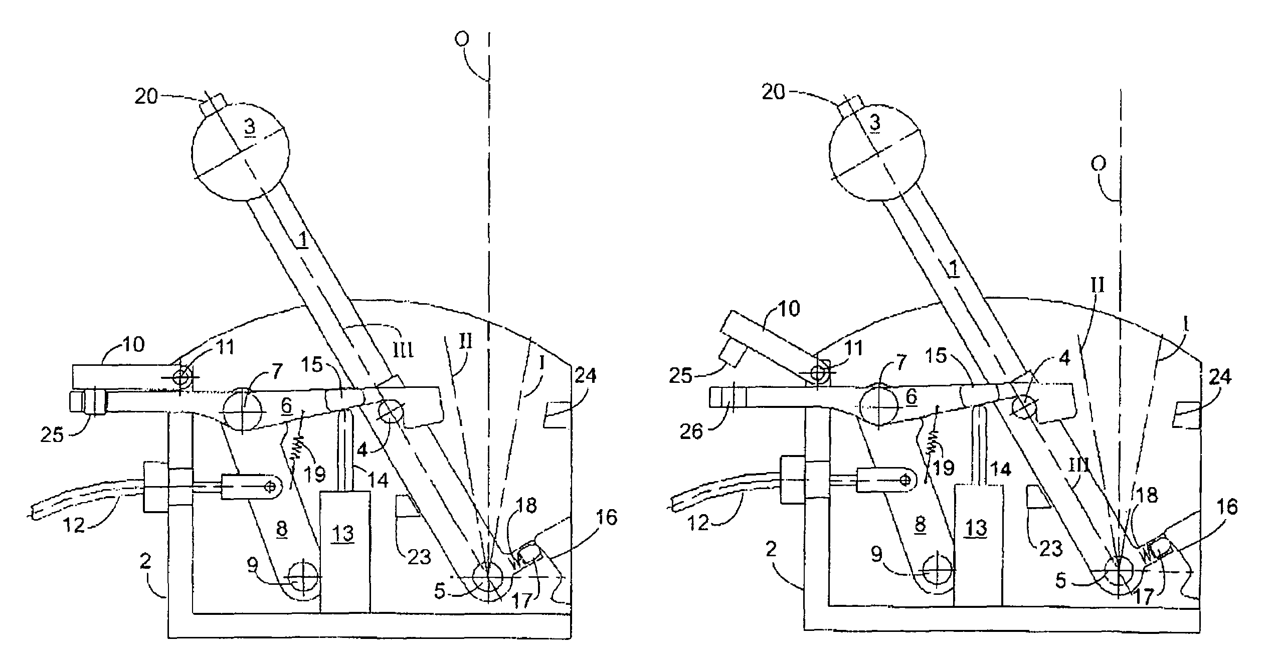
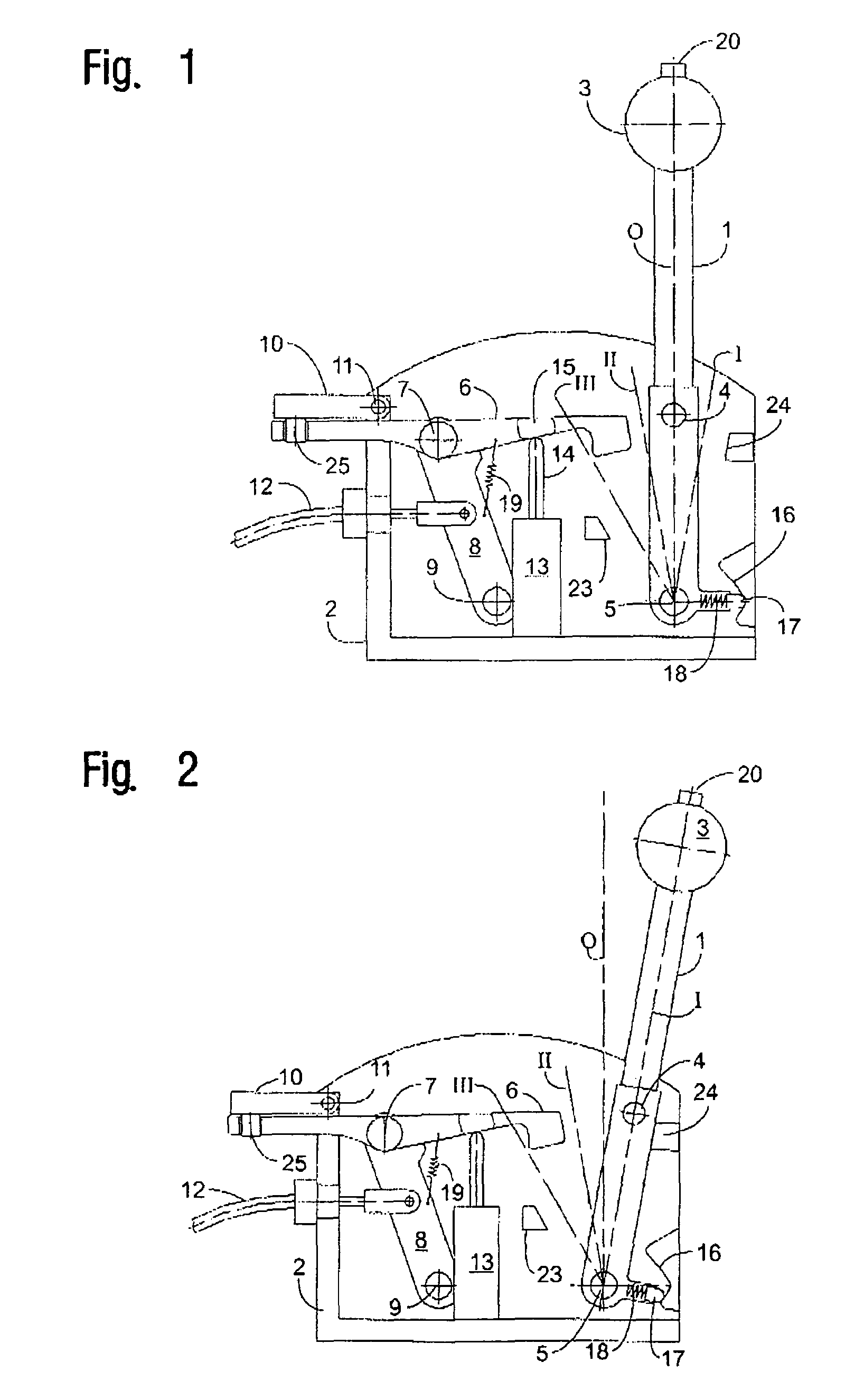
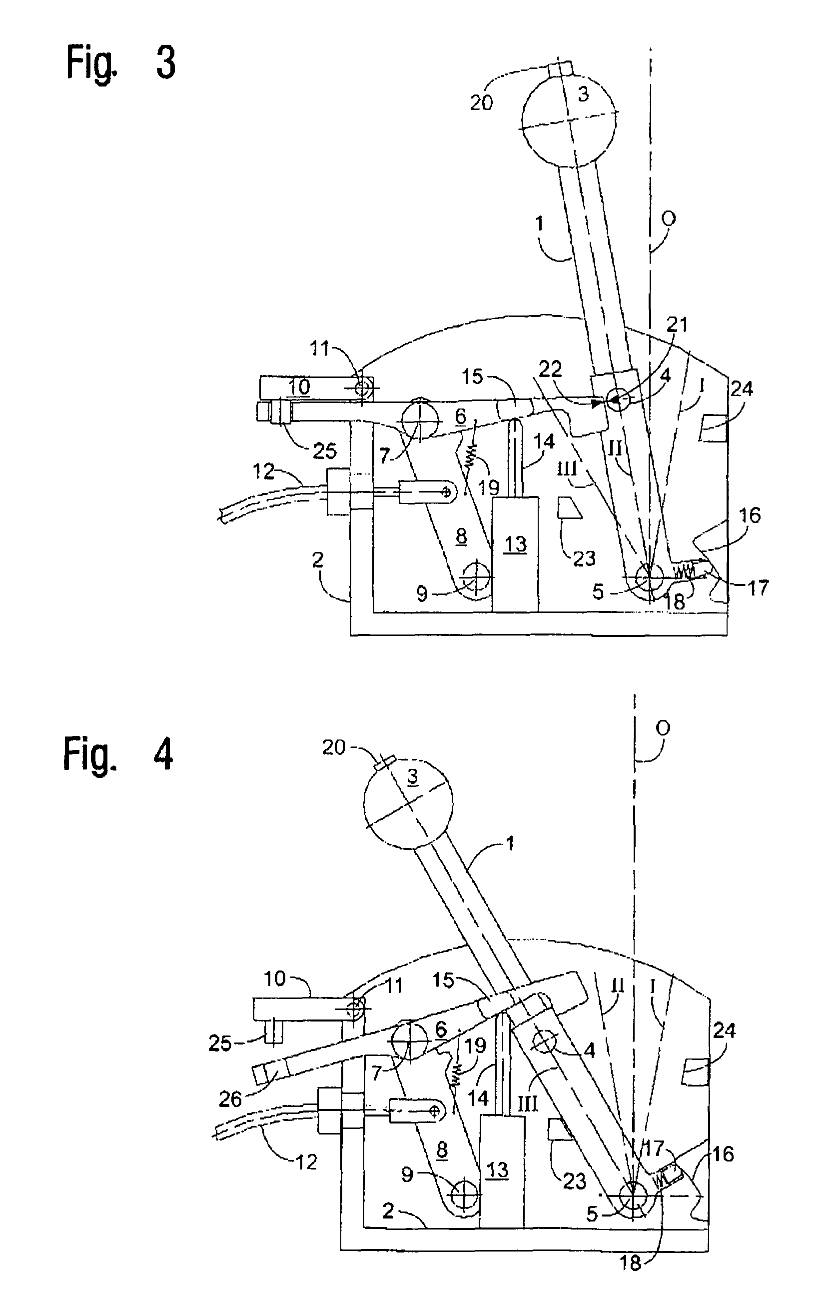
[0033]FIG. 1 shows a schematic view of a longitudinal section of a preferred shifting device according to the present invention. Obvious and known individual parts of the shifting device are not shown for clarity's sake, and the presentation was limited to the essential functional structural components of the embodiment according to the invention. For example, the generally known detection devices for detecting a particular shift position are not shown.

[0034]FIG. 1 shows the shifting device according to the present invention with a gearshift lever 1, which is mounted pivotably around a shift axis 5. A pin 4, which acts as a gearshift lever-side stop face, is located at the gearshift lever 1 on the side. The gearshift lever 1 has a shift knob 3 and, at the lower end, a right-angled extension, which accommodates a sliding element 17, which is pressed by a spring 18 elastically onto a curve 16 arranged on the housing side. The curve 16 is designed such that the gearshift lever 1 stabil...


PUM


Abstract

A shifting device for the preferably powerless transmission of shift commands to a fully automatic or semi-automatic transmission of a motor vehicle and a frame and/or housing and a gearshift lever mounted pivotably along a shift gate. A first shift stop and a second shift stop are provided for the gearshift lever which each define a shift position for the said gearshift lever. At least one detection device is provided for detecting the shift position(s). An inoperative position is provided into which the gearshift lever pivots back by itself from the deflected shift position, driven by a restoring force. The shifting device has an actuating device, which can countermand a shift stop, so that the gearshift lever can be pivoted beyond the shift position(s) defined by this shift stop.

Description

CROSS REFERENCE TO RELATED APPLICATIONS[0001]This application claims the benefit of priority under 35 U.S.C. § 119 of German patent application DE 103 15 644 filed Apr. 4, 2003 the entire contents of which are incorporated herein by reference.FIELD OF THE INVENTION[0002]The present invention pertains a shifting device for the preferably powerless transmission of shift commands to a fully automatic or semi-automatic transmission of a motor vehicle with a frame and / or housing, a gearshift lever mounted pivotably along a shift gate, and a first shift stop and a second shift stop for the gearshift lever, which determine a shift position each of the gearshift lever. Such a shifting device has at least one detection device for detecting the shift positions, wherein an inoperative position, into which the gearshift lever pivots back by itself from a deflected shift position, driven by a restoring force, is arranged between these shift positions.BACKGROUND OF THE INVENTION[0003]A shifting d...

Claims


Application Information

Patent Timeline
IPC IPC(8): B60K17/04F16H59/02F16H59/10F16H61/22F16H63/48
CPCF16H59/10F16H61/22F16H59/0204F16H63/48F16H2059/0295Y10T74/2014F16H2061/223Y10T74/2003Y10T74/20098Y10T74/20043Y10T74/2011F16H2059/0239
Inventor GIEFER, ANDREASMEYER, JORG
Owner ZF FRIEDRICHSHAFEN AG
Why Eureka
Try Eureka