

Stapling and cutting in resectioning for full thickness resection devices
a resection device and full-thickness technology, applied in the field of stapling tissue, can solve the problems of difficult manipulation of sutures from outside the body, often unwieldy devices,
- Summary
- Abstract
- Description
- Claims
- Application Information
AI Technical Summary
Problems solved by technology
Method used
Image

Examples
first embodiment
[0032]The orientation and movement of the components in the first embodiment is shown in FIG. 2A. The stapling head 52 may be rotatably mounted within the first casing 10 so that, in a first position, the staple firing edge 54 is adjacent to the anvil 12. The stapling unit 1 may rotate, for example, about an axis substantially parallel to a longitudinal axis 14 of the first casing 10. Then, the staple head 52 is rotated relative to the first casing 10, to a second position.
[0033]An alternative orientation and movement of the components is shown in a second embodiment of a device according to the present invention, shown in FIG. 2B. In the second embodiment, the stapling head 52′ may be movably mounted in a longitudinal direction within the first casing 10′ so that, in a first position, the staple firing edge 54′ is adjacent to the anvil 12′. The stapling unit 1′ may move longitudinally, for example, parallel to an axis substantially parallel to a longitudinal axis 14′ of the first c...
fourth embodiment
[0037]a device according to the present invention shown in FIGS. 5A and 5B is similar to the first embodiment except that in the fourth embodiment, the stapling unit 1′″ may also have a tissue cutter 90. The tissue cutter 90 enables the stapling unit 1′″ to be used, for example, for full thickness resectioning procedures during which a portion of tissue below the staple line is severed and removed from the body lumen 4 for testing.
[0038]The orientation and movement of the components in the fourth embodiment is shown in FIG. 6A. The cutting edge 94 may be rotatably mounted within the first casing 10′″ so that, in a first position, the cutting edge 94 is adjacent to a side 25 of the window 20′″ which is substantially parallel to a longitudinal axis 14′″ of the first casing 10′″. The tissue cutter 90 may rotate, for example, about an axis substantially parallel to a longitudinal axis 14′″ of the first casing 10′″. Then, the cutting edge 94 is rotated relative to the first casing 10′″ t...
seventh embodiment
[0044]In a seventh embodiment detailed in FIG. 9, the stapling unit 1″″″ operates similarly as described above, but is comprised of three concentric tubes 11″″″, 71″″″ and 111″″″ with windows 20″″″, 80″″″, and 120″″″ which form an opening 124″″″ from an interior 16″″″ of the stapling unit 1″″″ to an exterior 17″″″ of the stapling unit 1″″″. One edge 26″″″ of the window 20″″″ on the first tube 11″″″ forms an anvil 12″″″. The stapling device 50″″″ is mounted to second tube 71″″″ which is movably mounted within the first tube 11″″″, and an edge 84″″″ on the window 80″″″ on the second tube 71″″″ forms a staple firing edge 54″″″ which faces the anvil 12″″″. The tissue cutter 90″″″ is mounted to the third tube 111″″″ which is movably mounted within the second tube 71″″″ and the first tube 11″″″, and an edge 124″″″ of the window 120″″″ on the third tube 111″″″ forms the cutting edge 94″″″.
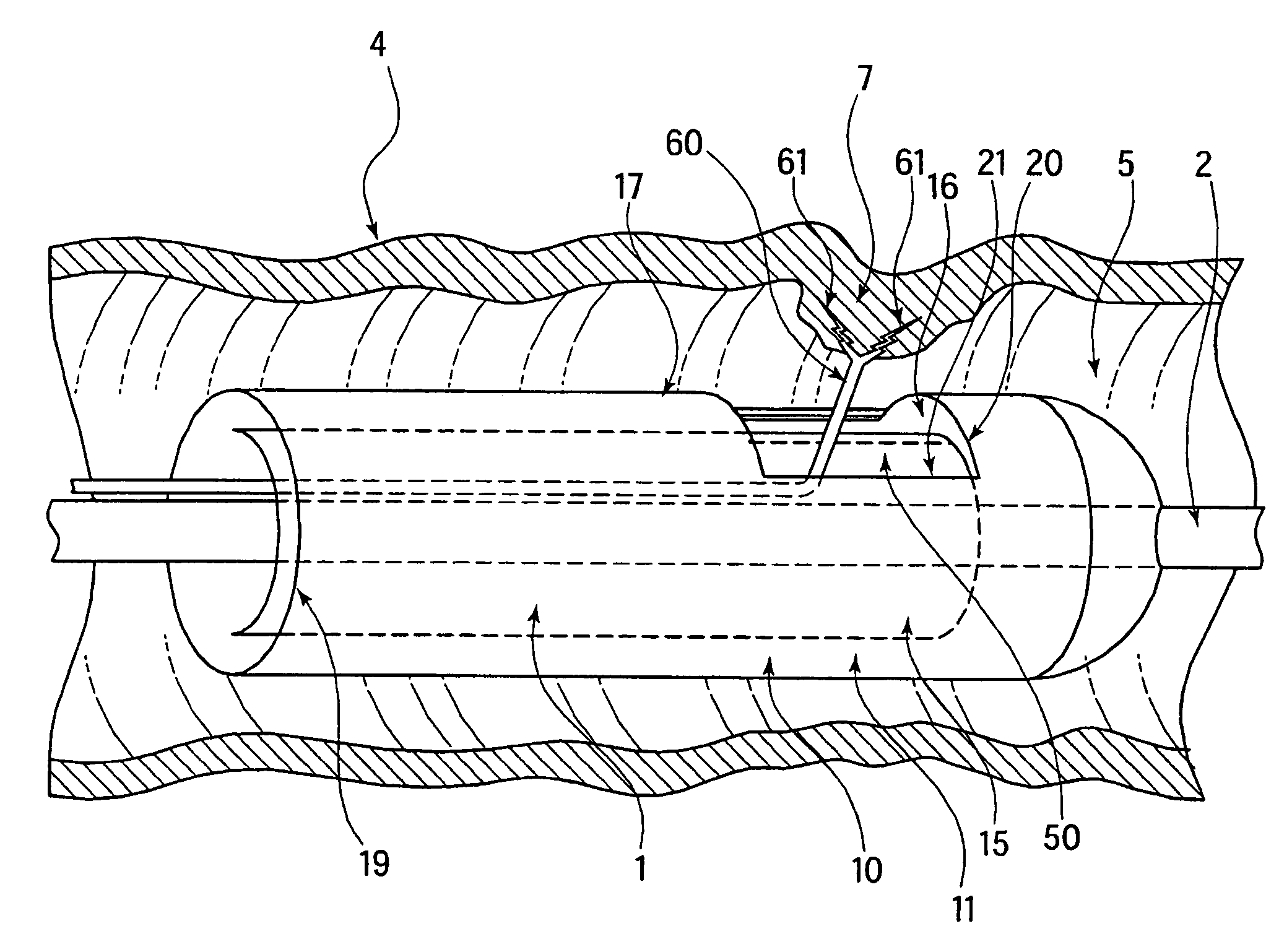
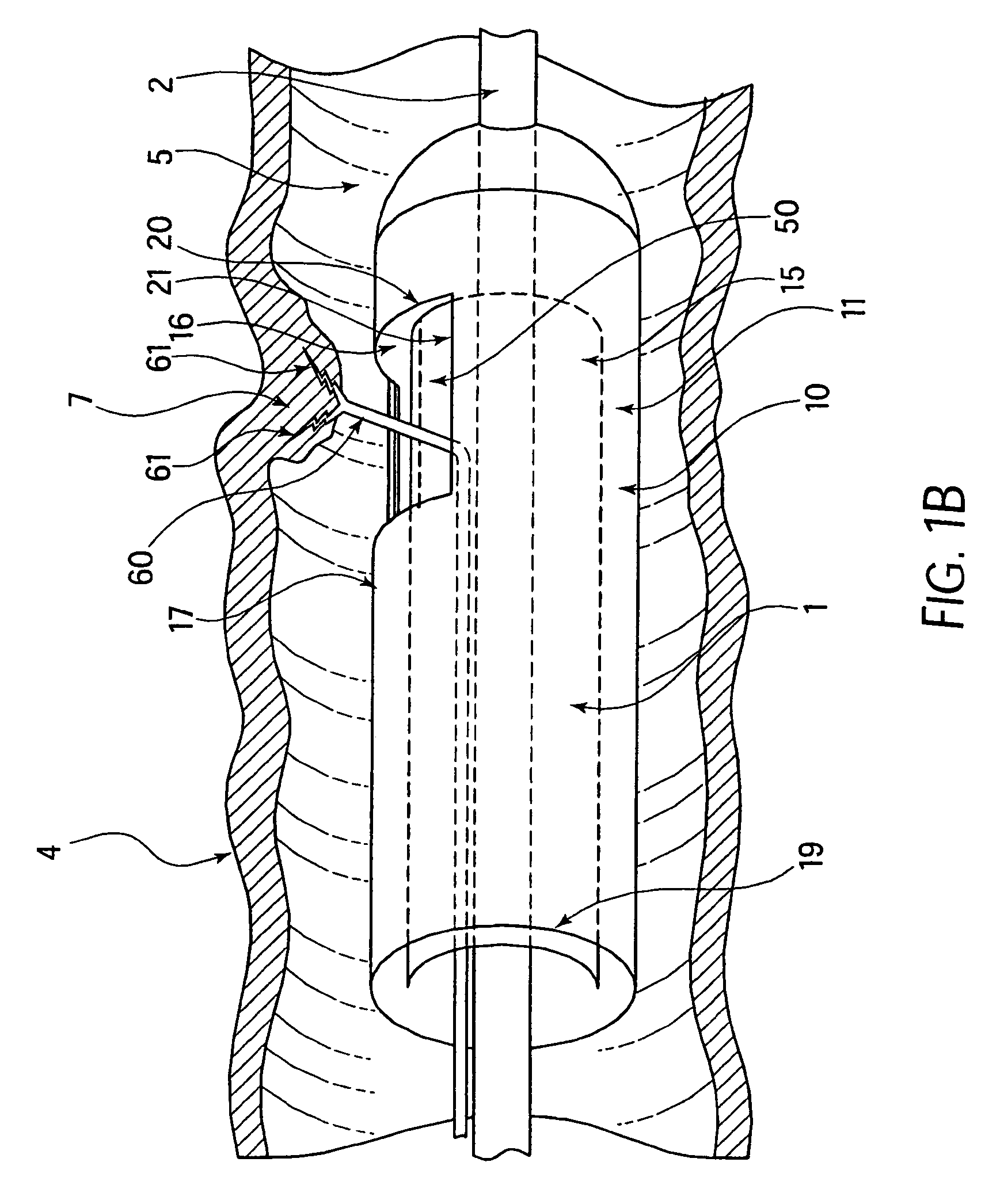
[0045]Any of the embodiments of the present invention may optionally include a tissue grasper 60 (deta...
PUM
| Property | Measurement | Unit |
|---|---|---|
| Flexibility | aaaaa | aaaaa |
| Strength | aaaaa | aaaaa |
Abstract
Description
Claims
Application Information