Board to board connector

a board to board connector and connector technology, applied in the direction of coupling contact members, fixed connections, coupling device connections, etc., can solve the problems of poor resilience restoring ability of the elastic contact portion, adverse use effect, and failure to meet the needs of use, so as to improve the efficiency of terminal use and high insertion durability

Inactive Publication Date: 2008-02-26
ADVANCED CONNECTEK INC
View PDF6 Cites 38 Cited by
  • Summary
  • Abstract
  • Description
  • Claims
  • Application Information

AI Technical Summary

Benefits of technology

[0006]It is a primary object of the present invention to provide a board to board connector, which makes use of a two-way multi-layer U-shaped spring portion structure, to improve the terminal using efficiency and to meet the requirements of high insertion durability.
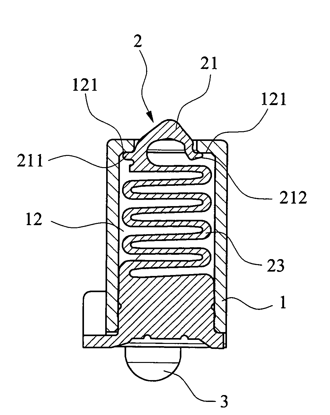
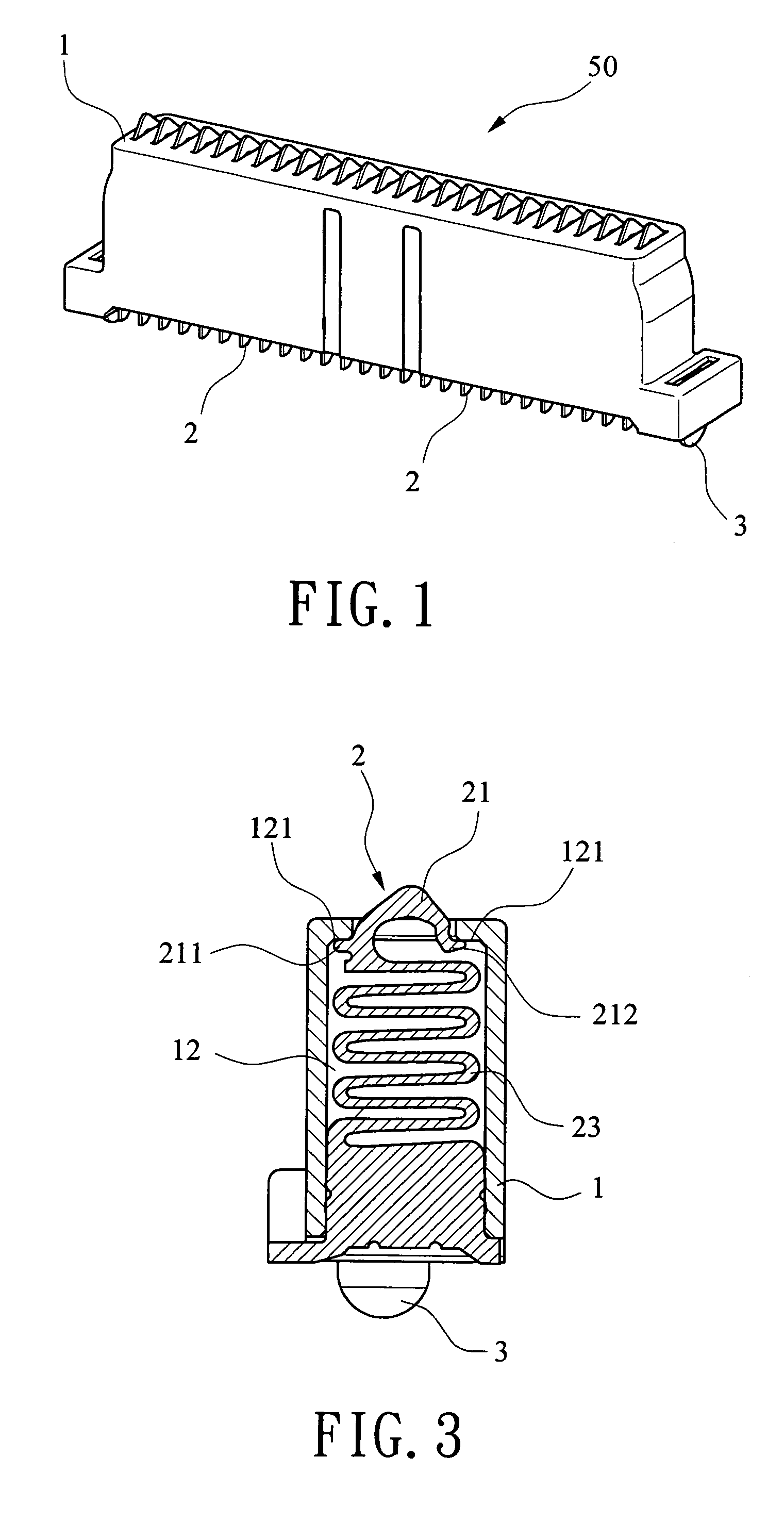
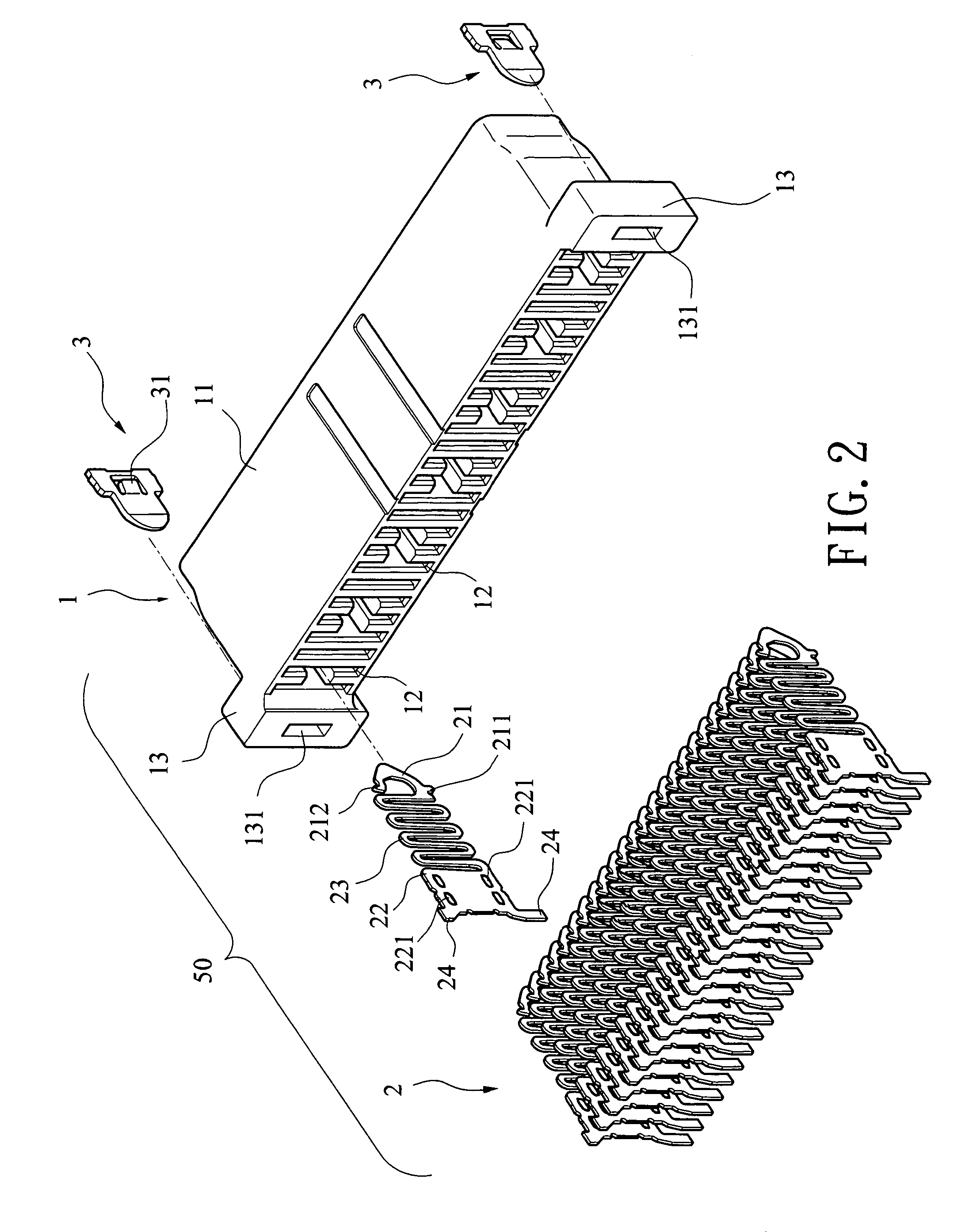
[0007]To achieve the above object, the present invention uses the following arts to achieve its functions. The board to board connector is in a vertical structure, which comprises an insulative housing, a plurality of electrical terminals and a pair of fastening members set on two sides of the insulative housing. Whereinto, the insulative housing has a body portion, the body portion being disposed with a plurality of terminal chambers which pass from the bottom face through the top face thereof for accommodating the electrical terminals. On two sides of the top portion of each terminal chamber, there is disposed with a guarding arm respectively. On two sides of the insulative housing along the axle direction thereof, there is disposed outward with a convex portion respectively, and on the convex portion having a wide slot. Each terminal includes a contact portion, a fixing portion and a two-way multi-layer U-shaped spring portion connected therebetween. The u-shaped spring portion has a perfect elasticity and a small deforming range and could draw back evenly, thus could provide a product of high insertion durability. The contact portion is provided with a stopping portion at the end connecting the spring portion, and on the other end forming an abutting portion. When electrical terminals are assembled within terminal chambers, the stopping portion and the abutting portion could abut against the guarding portions of the terminal chamber to stabilize the terminal. On two sides of the fixing portion, there is formed with multiple crisscross interfering portions which could engage with the walls of the terminal chamber. Along two side edges of the fixing portion, each extends outward a solder leg. The fastening members could be connected with the PCB after being disposed in the insulative housing, the solder legs of the connector are soldered to the PCB to achieve stability and connection, then contact portions abut against another PCB, thus the terminals are connected with upper and lower two pieces of PCBs to achieve stable signal transmission among electronic devices.

Problems solved by technology

Firstly, the elastic contact portion (abutted against the PCB) and the mounting portion (mounted in the insulative housing) of the terminal define a relatively large angle, and the elastic contact portion surpasses the insulative housing largely, when the contact portion is contacted with the PCB, they need to apply a strong force to press them to the same level with the upper surface of the insulative housing, which is adverse for operation, and the resilience restoring ability of the terminal is relatively poor.
Secondly, as time passes, the elastic contact portion would become poor on restoring resilience and surpass further out of the insulative housing, which is adverse for using.

Method used


Image

  • Board to board connector
  • Board to board connector
  • Board to board connector

Examples


Embodiment Construction

[0012]Refer to FIG. 1, which shows a preferred embodiment of a board to board connector 50 of the present invention. The board to board connector 50 is of a vertical type structure, which comprises an insulative housing 1, a plurality of electrical terminals 2 and a pair of fastening members 3 for fastening to a PCB. Please refer to FIGS. 2 and 3 for the full view of the said connector, a greater detail of the board to board connector 50 will be described in detail later.

[0013]Referring to FIGS. 1-3, the insulative hosing 1 has a body portion 11, the body portion 11 being disposed with a plurality of terminal chambers 12 which pass from the bottom face through the top face thereof for accommodating the electrical terminals 2. The terminal chambers 12 are partition-liked, every two terminal chambers 12 separated by a single terminal chamber 12 are communicated with each other so as to be apt to part processing, it is also could reduce the resistance when assembling the electrical ter...


PUM


Abstract

The present invention is to provide a board to board connector, which comprises an insulative housing, a plurality of electrical terminals and a pair of fastening members. The insulative housing has a plurality of terminal chambers which pass from the bottom face through the top face of the base portion thereof for accommodating the electrical terminals. Each terminal includes a contact portion, a fixing portion and a two-way multi-layer U-shaped spring portion connected therebetween. The spring portion has perfect elasticity, and the contact portion is formed with a stopping portion at the end connecting the spring portion, and on the other end forming an abutting portion, which could match with the insulative housing effectively. The fastening members are disposed in the wide slots on two side convex portions of the insulative housing to connect with the PCB to achieve signal transmission.

Description

BACKGROUND OF THE INVENTION[0001]1. Field of the Invention[0002]The present invention relates to a board to board connector, particularly to a board to board connector in which the spring portion has a two-way multi-layer U-shaped structure with perfect resilience and low shrink range, to meet the requirements of high insertion durability.[0003]2. Description of Related Art[0004]Board to board connector mounted, between printed circuit boards (PCBs) is used to provide signal transmission among electronic devices. At present, the board to board connector has two configurations. One is the connector consists of a plug and a receptacle connector, the other is only a simplex connector used alone, i.e. it is a single connector in which the solder portion and contact portion thereof are each connected with a PCB to achieve signal transmission, the structure of this kind of board to board connector is relatively simple.[0005]For example, U.S. Pat. Nos. 6,276,941 and 6,142,790, both disclos...

Claims


Application Information

Patent Timeline
Patent Type & Authority Patents(United States)
IPC IPC(8): H01R13/24H01R12/71H01R12/77H01R13/05
CPCH01R13/2428H01R12/52H01R12/714
Inventor DWAN, SWU-LINWUAN, MICKEY
Owner ADVANCED CONNECTEK INC
Why Eureka
Try Eureka