Electronic apparatus

a technology of electronic equipment and auxiliary components, applied in the direction of instruments, carrier covers, casings/cabinets/drawer details, etc., can solve the problems of reducing the value of the car, affecting the performance of the car, and affecting the interior feeling of the high-grade interior, so as to reduce the clearance

Active Publication Date: 2008-02-26
PANASONIC CORP
View PDF20 Cites 40 Cited by
  • Summary
  • Abstract
  • Description
  • Claims
  • Application Information

AI Technical Summary

Benefits of technology

[0009]An object of the invention is to provide an electronic apparatus capable of reducing a clearance between a movable member and an apparatus body such as a frame member.

Problems solved by technology

Dust enters the apparatus through the clearance 8 so that failures may be caused.
There is also a problem in that the feeling of high grade of the interior is damaged and the value of the car is reduced if a clearance such as the clearance 8 is large.

Method used


Image

  • Electronic apparatus
  • Electronic apparatus
  • Electronic apparatus

Examples


first embodiment

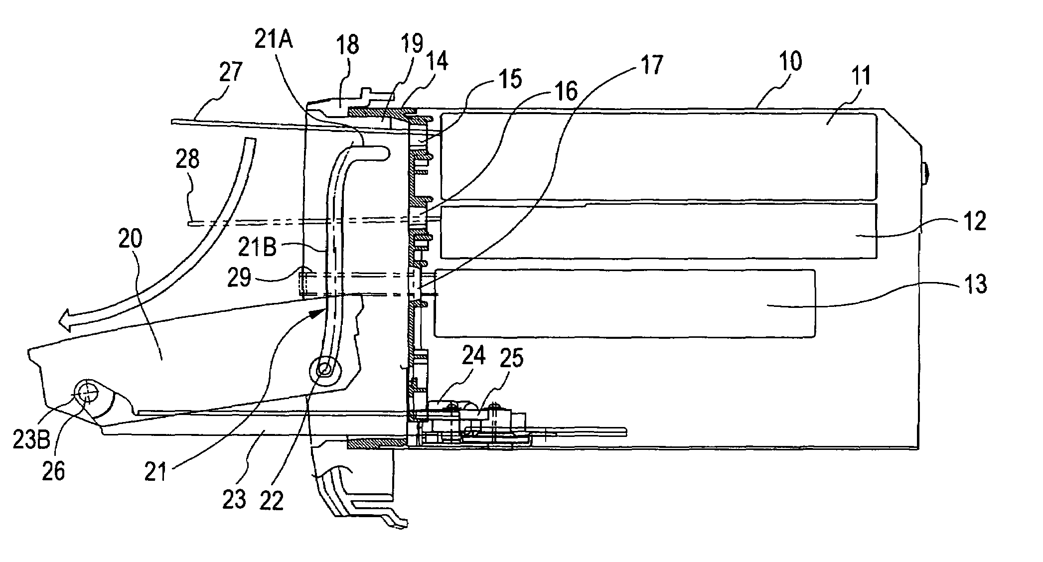
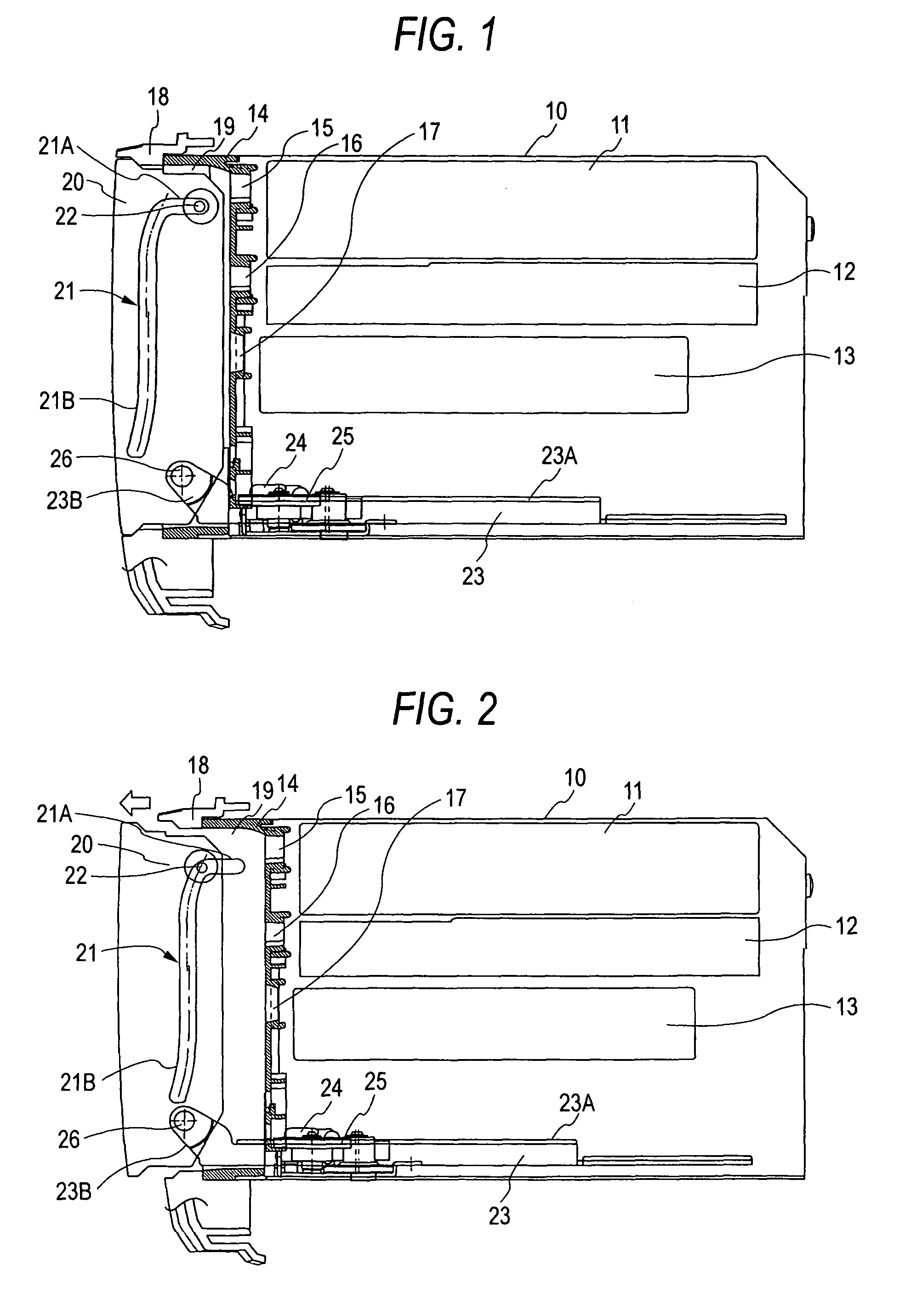
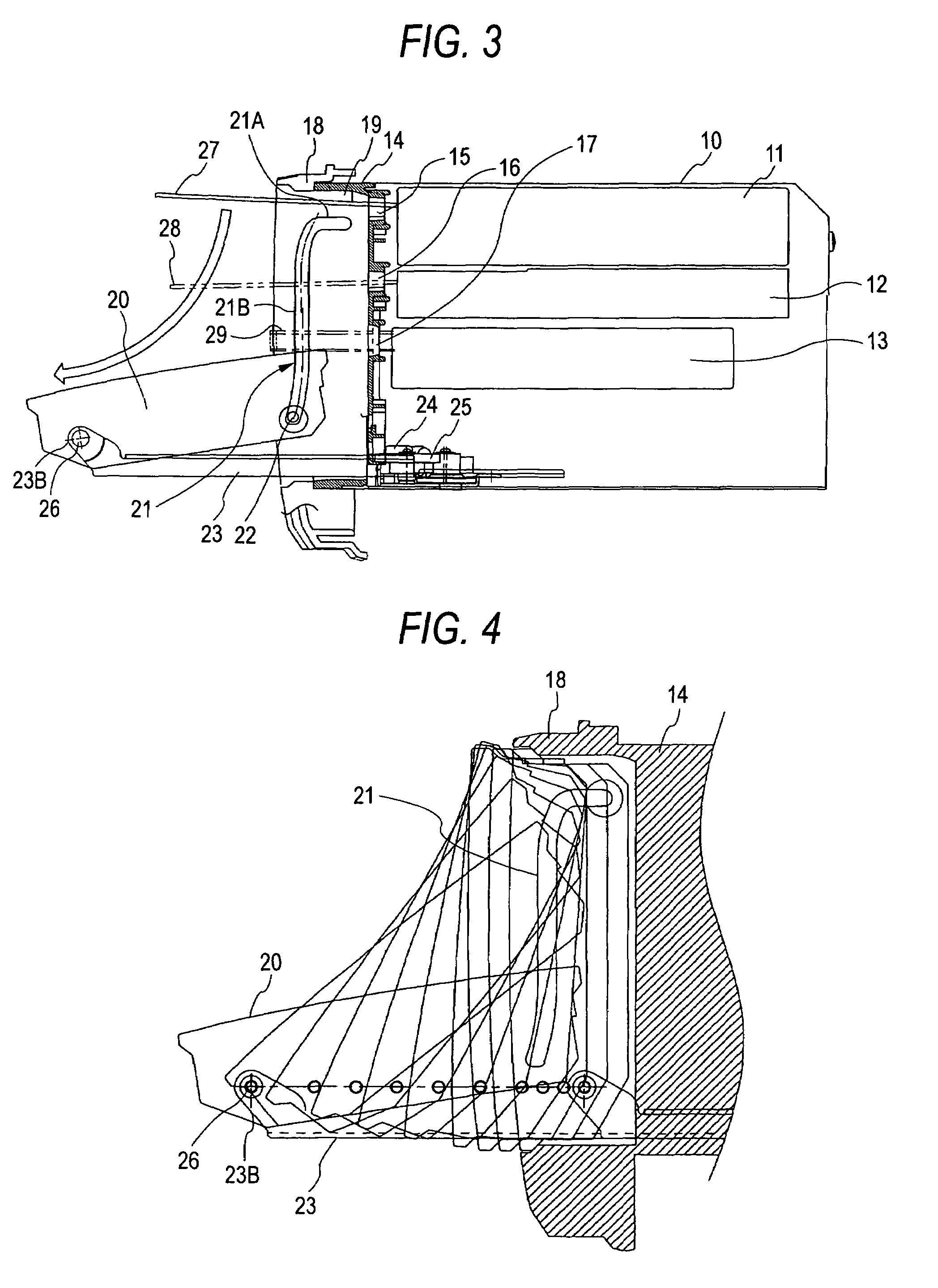
[0073]FIGS. 1 to 5 show an on-vehicle acoustic apparatus according to a first embodiment. In the embodiment, description will be given to an example that an electronic apparatus according to the invention is applied to the on-vehicle acoustic apparatus.

[0074]The on-vehicle acoustic apparatus has a housing 10, and a DVD player 11, a CD player 12 and a cassette tape player 13 are accommodated in the housing 10. Furthermore, a radio receiving circuit, an amplifying circuit and things like are accommodated in the housing 10. A first frame member 14 is attached and fixed to the opening portion of the front surface of the housing 10. The first frame member 14 is provided with a DVD insertion port 15 for inserting a DVD, a CD insertion port 16 for inserting a CD and a cassette tape insertion port 17 for inserting a cassette tape. A second frame member 18 is attached and fixed to the front end of the first frame member 14. The first frame member 14 and the second frame member 18 may be prov...

second embodiment

[0084]FIGS. 6 to 9 show a second embodiment. In FIGS. 6 to 9, the same portions as those in the first embodiment shown in FIGS. 1 to 5 have the same reference numerals.

[0085]In FIGS. 6 to 9, numeral “31” denotes a guide groove formed on the internal wall surface in the upper part of a frame member 18. Concave portions 32A and 32B are formed on both wall surfaces in the middle part of the guide groove 31, and rubber pads 33A and 33B are attached to the concave portions 32A and 32B. The opposed surfaces of the rubber pads 33A and 33B are arcuate surfaces. The same guide groove is formed on an internal wall surface in the lower part of the frame member 18. Numeral “34” denotes a projection formed on the upper surface of a movable member 20, and the same projection is formed on the lower surface of the movable member 20.

[0086]When a sliding plate 23 moves backward and then moves into a front concave portion 19 of the frame member 18 with the movable member 20 set in an almost vertical s...

third embodiment

[0087]FIGS. 10 to 12 show a third embodiment. In FIG. 10, numeral “10” denotes a housing, numeral “20” denotes a movable member supported on a first frame member 14 of the housing 10 to be rotated, and numeral “35” denotes an attachment piece formed on the left and right of the first frame member 14. A screw hole 36 and a positioning slot 37 are formed on the attachment piece 35. Numeral “18” denotes a second frame member. The movable member 20 is inserted into a square hole 38 on the center of the frame member 18. Numeral “39” denotes a jig. Protruded pieces 40A and 40B having triangular sections are formed on the back surface of the jig 39 in parallel. In the case that a body including the housing 10, the frame member 14 and the movable member 20 is attached to the frame member 18, the body is inserted from the back side of the square hole 38 of the frame member 18 and the protruded pieces 40A and 40B of the jig 39 are inserted from the surface side of the square hole 38 as shown ...


PUM

PropertyMeasurementUnit
timeaaaaaaaaaa
thicknessaaaaaaaaaa
structureaaaaaaaaaa

Abstract

When a sliding plate slides forward by the rotating force of a motor, the lower part of a movable member is driven and the movable member set in a vertical state moves forward with the vertical state maintained, and the movable member is then rotated and inclined. When the movable member is to be rotated, consequently, the upper and lower wall surfaces of the movable member do not abut on the internal wall surface of a front concave portion of frame members so that the rotation of the movable member is not hindered. Therefore, it is possible to provide an electronic apparatus having a movable member to be used in an on-vehicle acoustic apparatus and rotating a movable member to be accommodated in a frame member even if a clearance between the concave portion of the frame member and the movable member is reduced.

Description

BACKGROUND OF THE INVENTION[0001]1. Field of the Invention[0002]The present invention relates to an electronic apparatus to be used for an on-vehicle video acoustic apparatus.[0003]2. Description of the Related Art[0004]A conventional on-vehicle acoustic apparatus having a movable display section has been described in JP-A-5-63375, for example. In FIG. 21, numeral “1” denotes a frame member attached to the front surface of a housing and a movable member 3 is accommodated in a front concave space 2 of the frame member 1. The movable member 3 is provided with a liquid crystal display and an operation switch. A guide groove 4 is formed in a vertical direction on the left and right internal wall surfaces of the front concave space 2 of the frame member 1. Numeral “5” denotes a shaft provided in the upper parts of the left and right side surfaces of the movable member 3. The shaft 5 is inserted in the guide groove 4 of the front concave space 2. A sliding plate 6 is slidably supported on...

Claims


Application Information

Patent Timeline
Patent Type & Authority Patents(United States)
IPC IPC(8): G11B33/02B60R11/00B60R11/02G11B33/12H05K5/02H05K7/16
CPCB60R11/0211B60R11/0235G11B33/027G11B33/12B60R11/0205B60R2011/0084B60R2011/0085B60R2011/0092B60R11/02
Inventor SATO, NOBUHIROWAKITANI, MASATOSHI
Owner PANASONIC CORP
Why Eureka
Try Eureka