Method for manufacturing a shielded pole magnetic head for perpendicular recording

a manufacturing method and perpendicular recording technology, applied in the field of data storage devices, can solve the problems of high complexity of the plating process towards achieving the maximum possible magnetic moment, insufficient use of other methods of generating higher moment, such as sputtering, and insufficient use of the conventional perpendicular recording head employing a wide third shield layer

Active Publication Date: 2008-03-04
WESTERN DIGITAL TECH INC
View PDF10 Cites 178 Cited by
  • Summary
  • Abstract
  • Description
  • Claims
  • Application Information

AI Technical Summary

Problems solved by technology

The disparity between the width of the third shield layer and the track width of the pole tip creates a number of problems for the conventional perpendicular recording head.
Plating process typically requires a high level of complexity towards achieving the maximum possible magnetic moment.
As a result, other methods of generating higher moment, such as sputtering, may not be adequately used with the conventional perpendicular recording head employing a wide third shield layer.
Another problem associated with a wide third shield layer is the manufacturing complexity and high cycle time required for manufacturing the conventional perpendicular recording head at the wafer level.
However, during planarization, pole tips and / or write gaps may be subjected to potential damage.
As a result, the planarization process must be performed in a high degree of exactness, which significantly contributes to the cycle time of the head.
Yet another problem encountered with manufacturing a conventional perpendicular recording head employing a wide third shield layer lies in the fabrication of the pole tip.
However, during this process, there exists a possibility of track width variation and pole tip thickness variation when using a metal mask; and, when using an aluminum mask or a hard mask this poses another challenge in the removal of the mask.
In either case, it would be relatively difficult to implement these two processes.

Method used


Image

  • Method for manufacturing a shielded pole magnetic head for perpendicular recording
  • Method for manufacturing a shielded pole magnetic head for perpendicular recording
  • Method for manufacturing a shielded pole magnetic head for perpendicular recording

Examples


Embodiment Construction

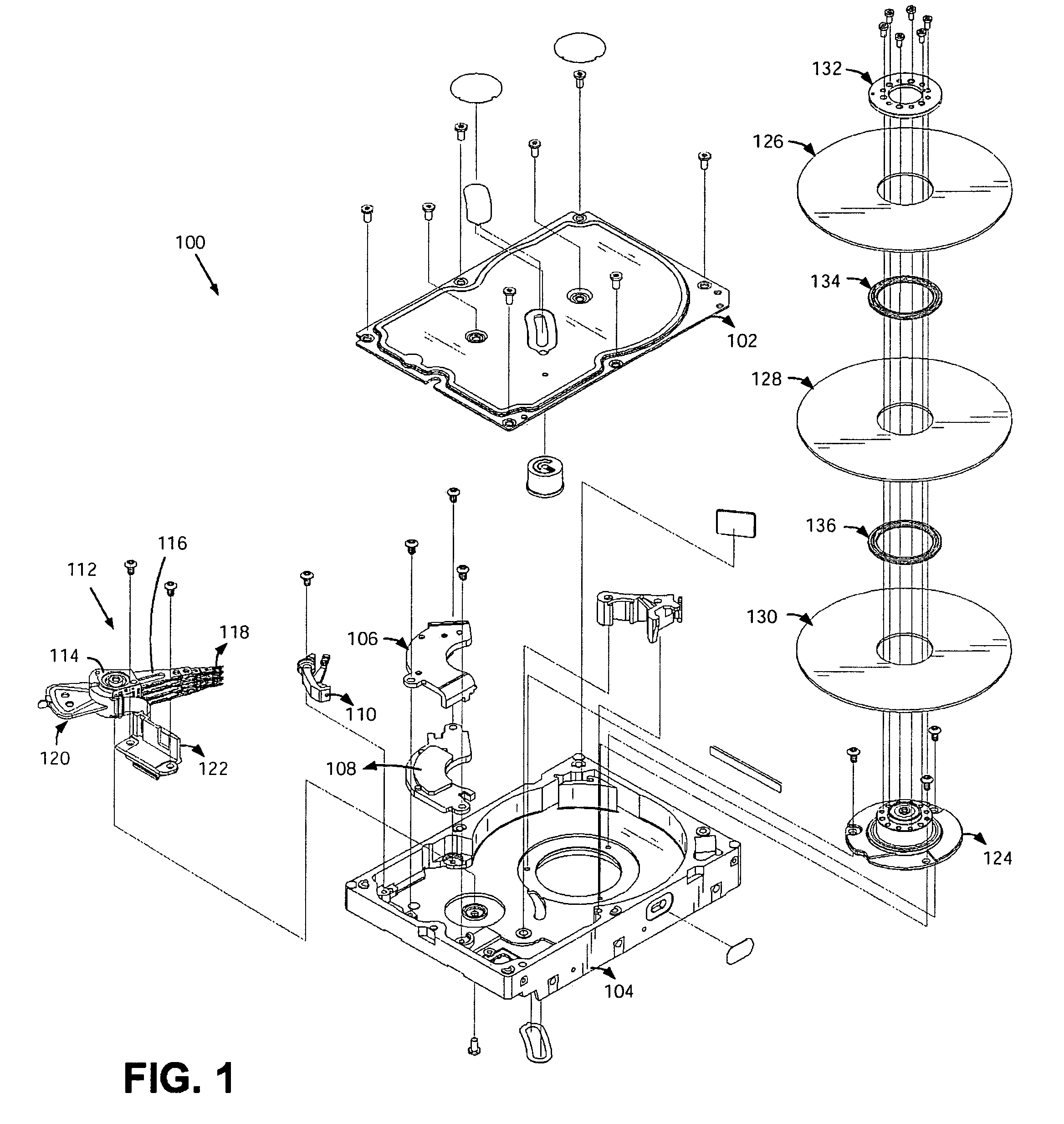
[0026]FIG. 1 illustrates a hard disk drive 100 in which an embodiment of the present invention may be used. An enclosure of the hard disk drive 100 comprises a cover 102 and a base 104. The enclosure is suitably sealed to provide a relatively contaminant-free interior for a head disk assembly (HDA) portion of the hard disk drive 100. The hard disk drive 100 also comprises a printed circuit board assembly (not shown) that is attached to base 104 and further comprises the circuitry for processing signals and controlling operations of the hard disk drive 100.

[0027]Within its interior, the hard disk drive 100 comprises a magnetic disk 126 having a recording surface typically on each side of the disk, and comprises a magnetic head or slider that may suitably be a magneto-resistive (“MR”) head such as a GMR head. The GMR head has an MR element for reading stored data on a recording surface and an inductive element for writing data on the recording surface. The exemplary embodiment of the ...


PUM

PropertyMeasurementUnit
widthaaaaaaaaaa
thicknessaaaaaaaaaa
thicknessaaaaaaaaaa

Abstract

A method of making a perpendicular magnetic recording head for use in a data storage device includes forming a first pole layer, a second pole layer, a third pole layer, and a shield layer of a write section. The first pole layer, second pole layer, third pole layer, and shield layer are formed without using a chemical mechanical polishing process. The method next includes concurrently trimming the shield layer and a write pole that is defined by the third pole layer to a predetermined track width. In the trimming step, the shield layer is used as a mask for the write pole.

Description

CROSS REFERENCE TO RELATED APPLICATIONS[0001]This application is a divisional of U.S. patent application Ser. No. 10 / 819,533, entitled SHIELDED POLE MAGNETIC HEAD FOR PERPENDICULAR RECORDING, filed Apr. 6, 2004, incorporated herein by reference.FIELD OF THE INVENTION[0002]The invention generally relates to data storage devices such as disk drive. More specifically, the present invention provides a novel type of shielded pole magnetic head design for perpendicular recording comprised of double reversed coils and a ring-head like structure above the recording pole, and that further incorporates a novel design feature in form of a shielding element having approximately the same width as the recording pole track width. This new type of perpendicular recording head provides a significant advantage over a conventional recording head by significantly reducing manufacturing complexity and cycle time.BACKGROUND OF THE INVENTION[0003]A conventional perpendicular recording head typically emplo...

Claims


Application Information

Patent Timeline
Patent Type & Authority Patents(United States)
IPC IPC(8): G11B5/147
CPCG11B5/1278G11B5/31G11B5/313Y10T29/4905Y10T29/49032Y10T29/49046Y10T29/49041G11B2005/0029G11B5/3116
Inventor STOEV, KROUM S.LIU, FRANCIS H.WANG, YUGANG
Owner WESTERN DIGITAL TECH INC
Why Eureka
Try Eureka