Lighting fixture housing for suspended ceilings and method of installing same

a technology of suspended ceilings and lighting fixtures, applied in the field of lighting fixtures, can solve the problems of difficult installation, difficult manipulation of lighting fixtures that are several feet across through suspended ceiling grids, and inability to meet the requirements of lighting fixtures, etc., and achieve the effect of convenient and secure installation

Inactive Publication Date: 2008-03-04
OLDENBURG GROUP
View PDF24 Cites 48 Cited by
  • Summary
  • Abstract
  • Description
  • Claims
  • Application Information

AI Technical Summary

Benefits of technology

[0009]The present invention provides a lighting fixture that may be easily and securely installed in a suspended ceiling from below the ceiling. The lighting fixture may comprise only four separate pieces to be installed, two end caps, a reflector assembly, and a ballast box cover. The two end caps are first slid into position at opposite ends of an opening in a suspended ceilin...

Problems solved by technology

Actually placing the lighting fixture in position within the T-bar grid can, however, prove to be a challenge.
This, however, rarely is the case, as the space between the suspended ceiling grid and the permanent ceiling structure above typically does not provide enough room or access to allow the lighting fixture to be lowered into the suspended ceiling grid from above.
However, man...

Method used


Image

  • Lighting fixture housing for suspended ceilings and method of installing same
  • Lighting fixture housing for suspended ceilings and method of installing same
  • Lighting fixture housing for suspended ceilings and method of installing same

Examples


Embodiment Construction

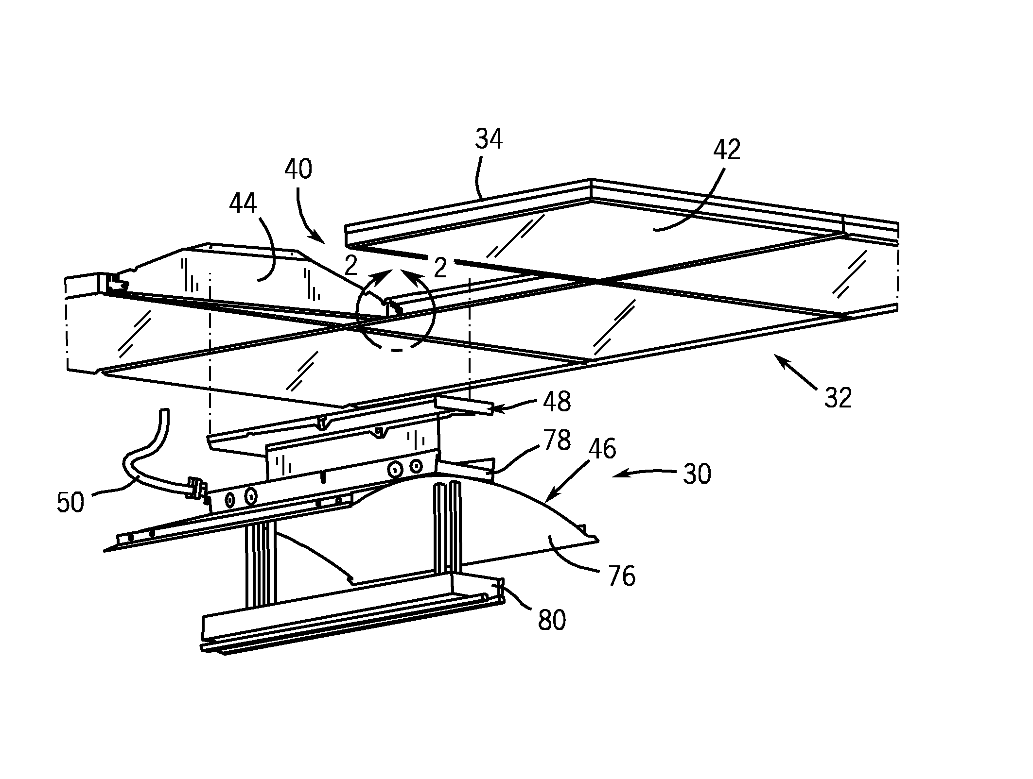
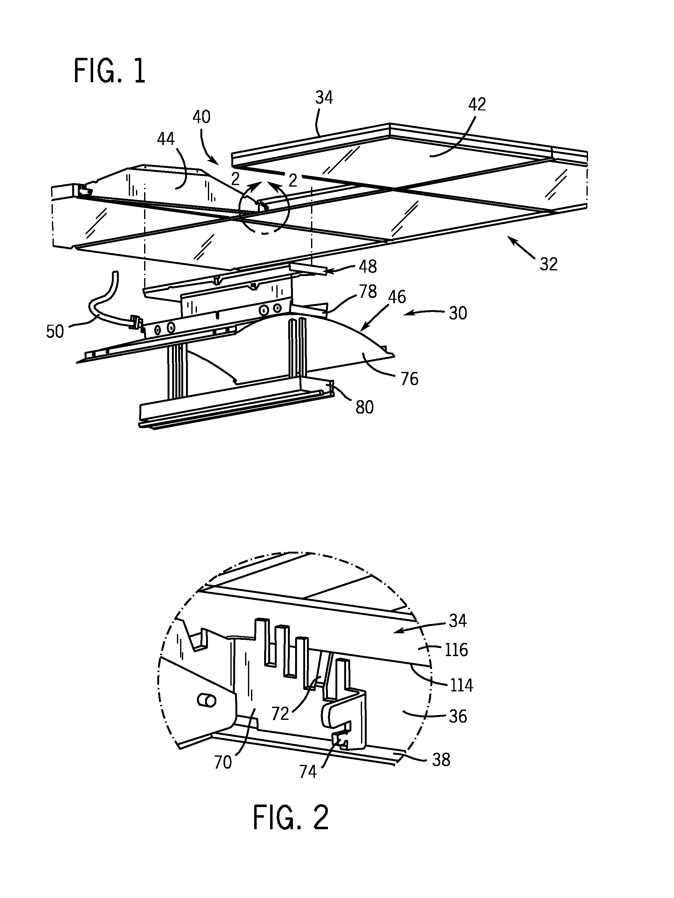
[0024]An exemplary lighting fixture in accordance with the present invention first will be described in detail herein, followed by a detailed description of a method for installing such a lighting fixture in a suspended ceiling. An exemplary lighting fixture 30 in accordance with the present invention for installation in a suspended ceiling 32 is illustrated in, and will be described in detail first with reference to, FIG. 1. As discussed above, a typical suspended ceiling 32 in which a lighting fixture 30 in accordance with the present invention may be installed is formed of a grid of T-bar beams 34. As illustrated in more detail in the view of FIG. 2, each of the T-bar beams 34 has a vertical rib 36 from the bottom of which horizontal flanges 38 extend along the length of the T-bar 34 to form the inverted T-shaped cross section thereof. The interlocked grid of T-bars 34 is suspended from a permanent ceiling or other structure located above the ceiling grid using wires and / or other...


PUM


Abstract

A lighting fixture housing includes two end caps, a reflector assembly, and a ballast box cover. The two end caps further include top and bottom flanges and mounting brackets having support tabs extending thereon. The lighting fixture housing is installed by first sliding the end caps into position at opposite ends of an opening in a suspended ceiling formed of a T-bar grid, and then attaching the reflector assembly to the end caps. The reflector assembly may be temporarily suspended from the end caps so that electrical connections to the assembly are made and the ballast box cover installed.

Description

[0001]This application claims the benefit of U.S. Provisional Patent Application No. 60 / 609,383, filed on Sep. 13, 2004.FIELD OF THE INVENTION[0002]The present invention pertains generally to lighting fixtures and, more particularly, to lighting fixtures to be installed in suspended or false ceilings and methods for installing such lighting fixtures.BACKGROUND OF THE INVENTION[0003]Suspended ceilings, sometimes also known as false ceilings, are very common features of commercial, retail and many other buildings. A suspended ceiling is formed of a grid that is suspended from a permanent ceiling or structure and ceiling tiles supported by the grid. The suspended ceiling grid is formed of a series of beam structures having a cross-section in the shape of an inverted T, i.e., having a vertical rib and two horizontal flanges extending from the bottom of the vertical rib along the length of the beam. Hereinafter these grid pieces will be referred to as T-bars. The T-bars forming the suspe...

Claims


Application Information

Patent Timeline
IPC IPC(8): F21S8/06
CPCE04B9/006F21S8/04F21S8/06F21Y2103/00
Inventor HASTINGS, MARK J.WILLMORTH, KEVIN L.
Owner OLDENBURG GROUP
Why Eureka
Try Eureka