Method for forming a terminal metal and terminal metal formed by the method

a terminal metal and metal technology, applied in the direction of permanent deformation connection, line/current collector details, electrical apparatus, etc., can solve the problems of wasteful dies and generation of performance variations, and achieve the effect of preventing failure and deformation of electric contact parts, reducing the cost of parts for respective constituent parts of terminal metals, and reducing the variation of performance caused by interchang

Active Publication Date: 2008-03-04
YAZAKI CORP
View PDF11 Cites 24 Cited by
  • Summary
  • Abstract
  • Description
  • Claims
  • Application Information

AI Technical Summary

Benefits of technology

[0010]Therefore, an object of the invention is to provide a terminal metal which is inexpensive and is free from variation to thereby exhibit a stable performance, and a method for forming the same terminal metal.
[0024]According to the invention, since parts can be shared between terminal metals that are to be formed under different product numbers, the minimization of variation in performance due to interchange caused for each part can be attained, and the parts costs for respective constituent parts of terminal metals can be reduced by virtue of mass production effect. Furthermore, before the electric contact parts and the wire connection parts are assembled together, work can be done only on the wire connection parts, thereby making it possible to prevent the failure and deformation of the electric contact parts during a wiring harness production process.
[0025]According to the terminal metals of the invention, since parts can be shared between terminal metals that are to formed under different product numbers, the minimization of variation in performance due to interchange caused for each part can be attained, and the parts costs for respective constituent parts of terminal metals can be reduced by virtue of mass production effect. Furthermore, before the electric contact parts and the wire connection parts are assembled together, work can be done only on the wire connection parts, thereby making it possible to prevent the failure and deformation of the electric contact parts during a wiring harness production process.

Problems solved by technology

Namely, since parts of the same shape are formed with different dies, there are caused problems that variation in performance is generated among the parts due to manufacturing tolerance of the shape, and that there are formed wasteful dies for forming parts of the same shape.

Method used


Image

  • Method for forming a terminal metal and terminal metal formed by the method
  • Method for forming a terminal metal and terminal metal formed by the method
  • Method for forming a terminal metal and terminal metal formed by the method

Examples


first embodiment

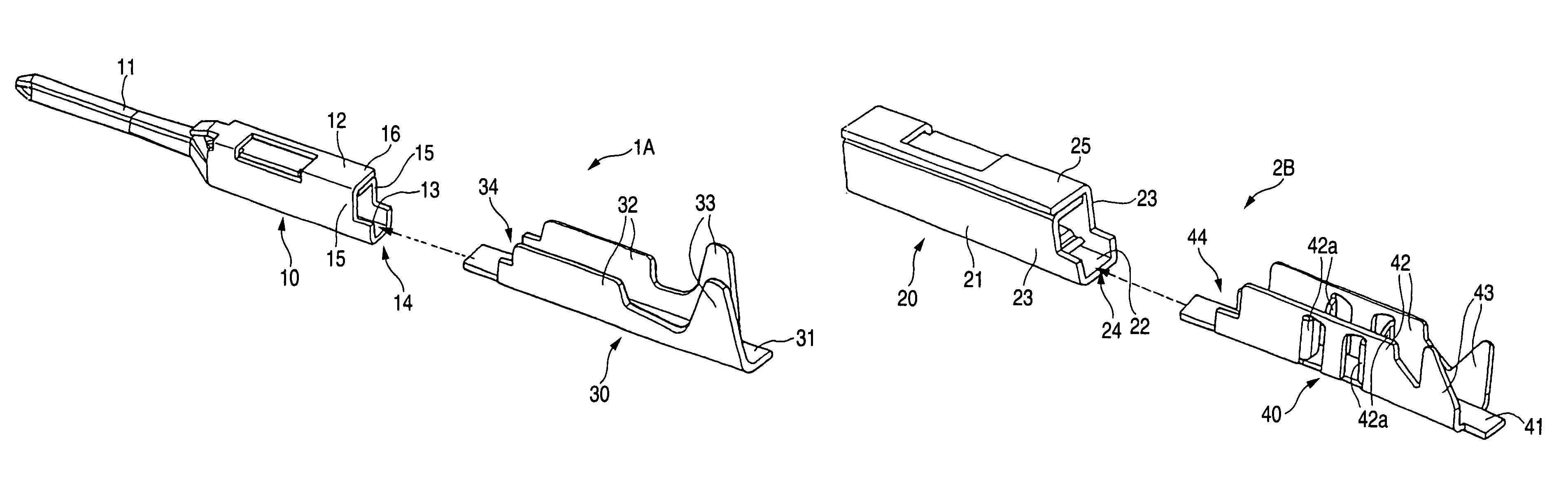
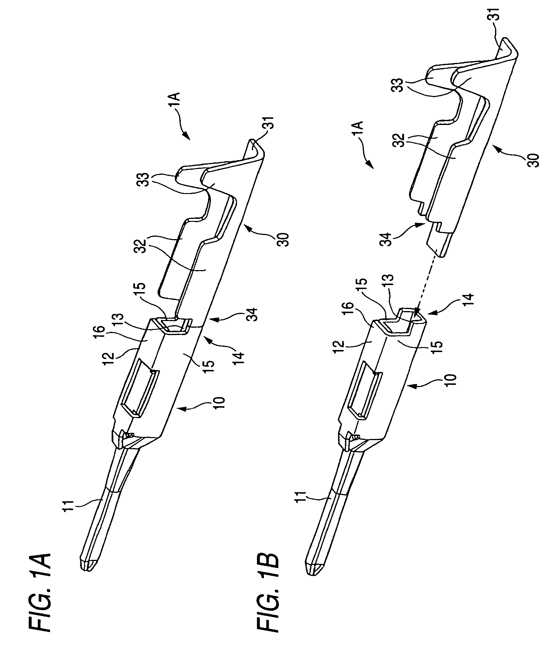
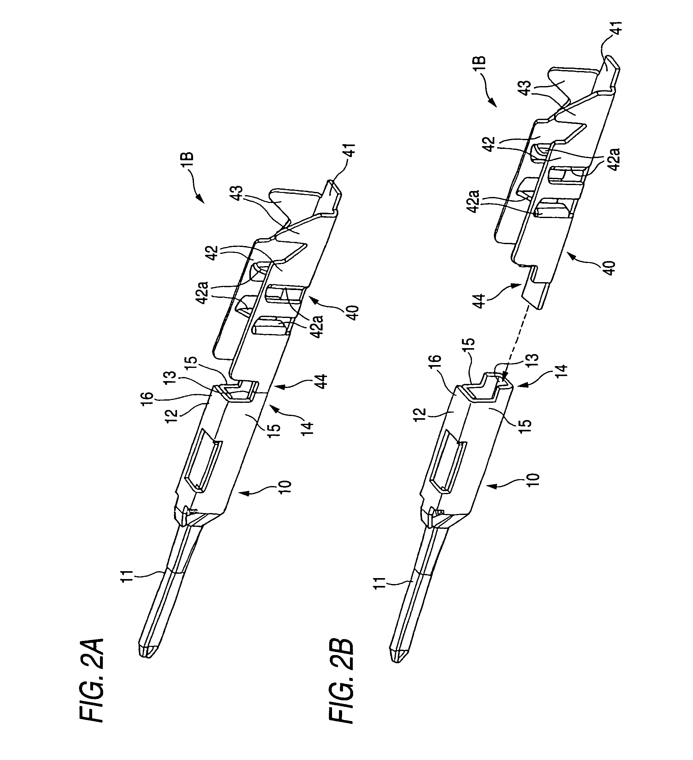
[0040]Hereinafter, a terminal metal and a method for forming the terminal metal according to a first embodiment of the invention will be described by reference to FIGS. 1A to 7. The terminal metal manufacturing method according to the first embodiment is a method for forming a terminal metal such as a clamp terminal 1A (shown in FIGS. 1A and 1B) having a male electric contact part (hereinafter, referred to as a male contact portion) 10, a crimp terminal 1B (shown in FIGS. 2A and 2B) having the male contact portion 10 and a piercing terminal 1C (shown in FIGS. 3A and 3B) having the male contact portion 10, and a terminal metal such as a clamp terminal 2A (shown in FIGS. 4A and 4B) having a female electric contact part (hereinafter, referred to as a female contact portion) 20, a crimp terminal 2B (shown in FIGS. 5A and 5B) having the female contact portion 20 and a piercing terminal 2C (shown in FIGS. 6A and 6B) having the female contact portion 20.

[0041]The terminal metals 1A, 1B, 1C...

second embodiment

[0077]Hereinafter, a terminal metal and a method for forming the terminal metal according to a second embodiment of the invention will be described by reference to FIGS. 9A to 14B. The terminal metal manufacturing method according to the second embodiment is a method for forming a terminal metal such as a clamp terminal 101A (shown in FIGS. 9A and 9B) having a male electric contact part (hereinafter, referred to as a male contact portion) 110, and a crimp terminal 101B (shown in FIGS. 10A and 10B) having the male contact portion 110, and a clamp terminal 102A (shown in FIGS. 11A and 11B) having a female electric contact part (hereinafter, referred to as a female contact portion) 120, and a crimp terminal 202B (shown in FIGS. 12A and 12B) having the female contact portion 120.

[0078]Note that the same reference numerals will be imparted to the constituent portions that is similar to those of the first embodiment, and the description thereof will be omitted.

[0079]In the second Embodime...


PUM

PropertyMeasurementUnit
conductiveaaaaaaaaaa
shapeaaaaaaaaaa
pressureaaaaaaaaaa

Abstract

A male contact portion, a female contact portion, a clamp portion where an electric wire is clamped for connection, a crimp portion where an electric wire is crimped and a piercing portion where an electric wire is pierced to be crimped are formed separately, whereby one of the male contact portion and the female contact portion is selected according to an application and one of the clamp portion, the crimp portion and the piercing portion is selected according to the application, and a connecting portion of the selected electric contact part and a connecting portion of the selected wire connection part are superposed on each other so as to join the selected electric contact making point and the selected wire connection part together.

Description

BACKGROUND OF THE INVENTION[0001]1. Field of the Invention[0002]The present invention relates to a method for forming a terminal metal used in a wiring harness and a terminal metal formed by the method.[0003]2. Related Art[0004]Various types of electronic appliances are installed on an automobile as a mobile body. Wiring harnesses are laid out on the automobile for supplying power and transmitting control signals to the electronic appliances so installed. The wiring harnesses each include a plurality of electric wires and a plurality of connectors. The electric wires are so-called covered wires each made up of a conductive core wire and an insulating coating portion which covers the core wire.[0005]The connectors each include a pair of insulating connector housings which are fitted together and conductive terminal metals which are housed in those housings. The terminal metals each include a wire connection part which is attached to an end portion of the electric wire so as to make a...

Claims


Application Information

Patent Timeline
Patent Type & Authority Patents(United States)
IPC IPC(8): H01R4/18
CPCH01R43/16Y10T29/49208Y10T29/49163Y10T29/49174
Inventor KUMAKURA, HIDETO
Owner YAZAKI CORP
Why Eureka
Try Eureka