
Fixing apparatus with controlled heating members for heating the outer surface of the fixing rotating member

a technology of rotating member and fixing apparatus, which is applied in the direction of electrographic process apparatus, instruments, optics, etc., can solve the problems of increasing the heat capacity of the external heating member. , to achieve the effect of increasing productivity, avoiding gloss variations

Inactive Publication Date: 2006-09-12
CANON KK
View PDF7 Cites 30 Cited by
  • Summary
  • Abstract
  • Description
  • Claims
  • Application Information

AI Technical Summary

Benefits of technology

The present invention provides a fixing apparatus that can adjust the amount of heat provided by external heating members to the surface of a fixing member, such as a heating fixing roll, and increase productivity even when printing on cardboards. The apparatus uses a plurality of external heating members and a first and second fixing rotating member to thermally fix a toner image on a recording material. The quantity of heat provided by the external heating members can be adjusted by varying the times or pressures at which they abut against the fixing rotating member, resulting in high-quality color images and consistent gloss.

Problems solved by technology

However, paper with a heavy basic weight absorbs much heat.
Accordingly, such paper requires a significantly larger quantity of heat for fixation than thin paper.
The above conventional techniques have the following problems.
However, with a mere increase in the quantity of heat provided by the external heating rolls, when the fixing apparatus fixes an image to transfer paper, if the external heating rolls provide a large quantity of heat to the surface of the heated member before the transfer paper enters a fixing portion, then the surface of the heated member becomes too hot.
This causes toner on the transfer member to be excessively melted to make the toner too glossy.
Thus, an attempt to control the external heating temperature or the temperature of the heated member cannot solve the above problems because of the insufficient thermal responsiveness of the external heating rollers or heated member.
Further, if an attempt is made to cause the external heating rolls to provide a quantity of heat to the surface of the heated member after the transfer paper has entered the fixing portion, the transfer paper absorbs heat from the heated member to make the heated member too cold.
It is thus impossible to effectively heat the surface of a fixing roll that is the heated member, using the external heating rolls.
This may in turn make it impossible to achieve a high productivity or vary the gloss of color images (gloss nonuniformity).
Therefore, disadvantageously, high-quality color images are not obtained.
However, in view of the deviation of timing of the abutment of the external heating rolls against the heated member and the deviation of timing of the entry of the transfer paper into the fixing portion, it is impossible to match the timing of entry of the transfer paper into the fixing portion with the timing of provision, by the external heating rolls, of a quantity of heat to the surface of the heated member.

Method used


Image

  • Fixing apparatus with controlled heating members for heating the outer surface of the fixing rotating member
  • Fixing apparatus with controlled heating members for heating the outer surface of the fixing rotating member
  • Fixing apparatus with controlled heating members for heating the outer surface of the fixing rotating member

Examples


first embodiment

(First Embodiment)

(1) Example of Image Forming Apparatus

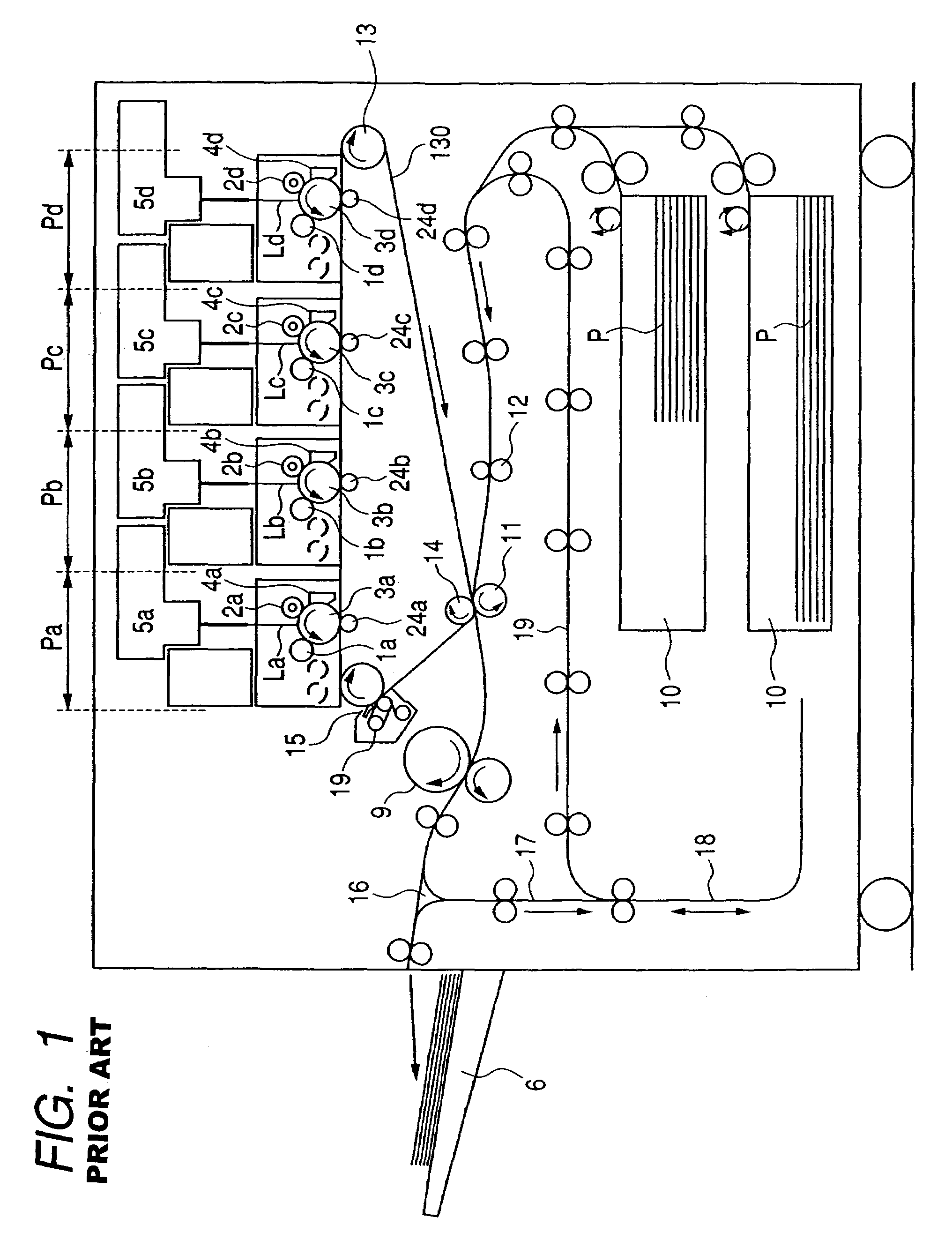
[0026]FIG. 1 is a schematic diagram showing the general configuration of an example of an image forming apparatus. The image forming apparatus according to the present example is a tandem type color laser printer using a transferring electrophotography process.

[0027]The image forming apparatus includes a first, second, third, and fourth image forming portions Pa, Pb, Pc and Pd. The image forming apparatus executes a latent image forming, developing, and transferring processes to form toner images in different colors.

[0028]The image forming portions Pa, Pb, Pc and Pd comprise exclusive image bearing members, in the present example, electrophotographic photosensitive drums 3a, 3b, 3c and 3d, respectively. Toner images in different colors are formed on the respective photosensitive drums 3a, 3b, 3c and 3d. An intermediate transfer member (intermediate transfer belt) 130 is installed adjacent to the photosensitive drums 3a, 3b, 3c ...

second embodiment

(Second Embodiment)

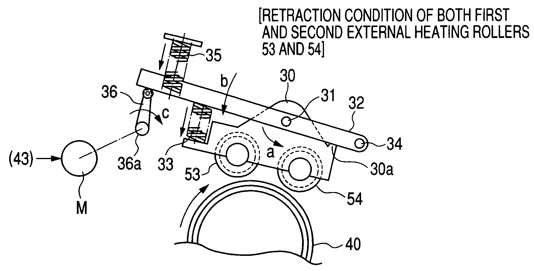
[0107]Second Embodiment will be described with reference to FIGS. 6A and 6B. The present embodiment is a fixing apparatus configured so as to sequentially increase the pressure at which the first and second external heating rollers 53 and 54 abut against the fixing roller 40 when a fixing operation is started.

[0108]The pressing arrangement and detachably mountable arrangement for the external heating members according to the present embodiment are the same as those shown in FIGS. 3A to 3C for First Embodiment except that they do not have the spring 33.

[0109]FIG. 6A shows that the first and second external heating rollers 53 and 54 are separate from the fixing roller 40. In this state, the pressure releasing arm 36 is turned in the direction of the arrow c to turn the external heating pressing arm 32 in the direction of an arrow b. Consequently, the external heating support frame 30, that is, the first and second external heating rollers 53 and 54, start to move to...


PUM


Abstract

The present invention provides an external heating member abutment controller which can instantaneously adjust the quantity of heat provided by external heating members to the surface of a fixing member, to provide a fixing apparatus which can drastically increase productivity for cardboards and which can provide high-quality color images free from variations in gloss (gloss nonuniformity). Thus, a fixing apparatus according to the present invention comprises a first and second fixing rotating members that use nip portions to thermally fix a toner image on a recording material and a first and second heating members that abut against the first fixing rotating member to heat an outer surface of the first fixing rotating member. The fixing apparatus is characterized in that when a fixing operation is started, the first heating member and the second heating member are sequentially abutted against the first fixing rotating member.

Description

BACKGROUND OF THE INVENTION[0001]1. Field of the Invention[0002]The present invention relates to a fixing apparatus for use in a printer, copier, facsimile machine, or the like which employs an electrophotographic system or an electrostatic recording system.[0003]2. Related Background Art[0004]Various image forming apparatuses are conventionally known. Of these image forming apparatuses, those based on an electrophotographic system have prevailed which exposes a photosensitive member to laser light and which then develops an image. Such an image forming apparatus has advantages such as a high image quality and high-speed operations and is widely used as, for example, an output apparatus such as a copier or a color laser beam printer.[0005]The color image forming apparatus such as a copier or a color laser beam printer has been requested to achieve high productivity (the number of prints per unit time) using various sheets (recording materials) such as cardboards.[0006]In order to in...

Claims


Application Information

Patent Timeline
Patent Type & Authority Patents(United States)
IPC IPC(8): G03G15/20
CPCG03G15/2017G03G2215/2019G03G15/2039
Inventor KAMEDA, SEIICHIRO
Owner CANON KK
Learn More