Fuel cell block including a water separator

a fuel cell and water separator technology, applied in the field of fuel cell blocks, can solve the problems of pipeline connections fundamentally susceptible to leakage, leakage in lines carrying operating gas, and particular risk to operating safety, so as to avoid a large number of sealing locations, increase the safety and reliability of the fuel cell block in the event of leakage, and save space

Inactive Publication Date: 2008-03-04
SIEMENS AG
View PDF18 Cites 3 Cited by
  • Summary
  • Abstract
  • Description
  • Claims
  • Application Information

AI Technical Summary

Benefits of technology

[0035]A fuel cell block of this type is distinguished by a number of fuel cell stacks which adjoin one another and are in each case separated from one another, for example, by intermediate plates. The operating gases and also the cooling water are guided through complex pipes or passages leading through the individual cascade stages of the fuel cell block. A large proportion of the pipes in the immediate vicinity of the fuel cell stack can be avoided by the formation of connecting passages inside one or more end plates at the end or between the cascade stages. This avoids a large number of sealing locations and saves the space which is used for the piping which is otherwise required.
[0036]It is expedient for the operating-medium control device to be a valve, an actuator, a sensor or a flow monitor. All these operating-medium control devices can be at least partially integrated in an end plate of a fuel cell block without difficulty. This avoids the need for sealing locations between an operating-medium control device of this type and piping, with the result that the safety and reliability of the fuel cell block with respect to faults caused by leaks is increased.

Problems solved by technology

These pipe connections are fundamentally susceptible to leaks.
In this context, leaks in lines which carry an operating gas represent a particular risk to operating safety, since the use of hydrogen-containing and oxygen-containing operating gases means that there is a risk of a fire and possibly even explosions around a leak.
When a fuel cell block is being used in a vehicle, an additional difficulty is that the fuel cell block is subject to shocks and vibrations.

Method used


Image

  • Fuel cell block including a water separator
  • Fuel cell block including a water separator
  • Fuel cell block including a water separator

Examples


Embodiment Construction

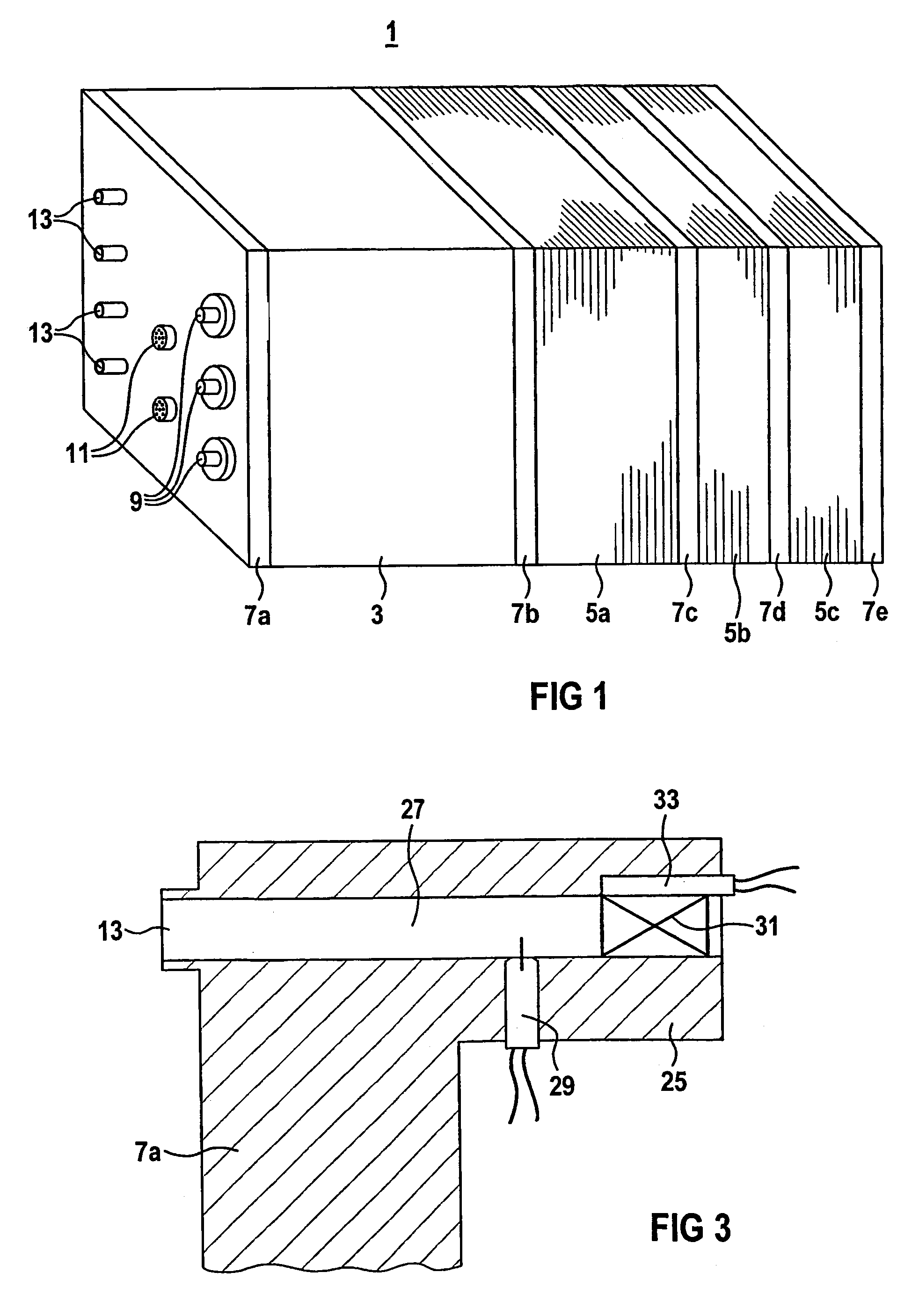
[0042]FIG. 1 shows a highly simplified and diagrammatic view of a fuel cell block 1 with a supply part 3, a humidifying cell stack 5a, and two fuel cell stacks 5b, 5c comprising PEM fuel cells. The stacks form two cascade stages of the fuel cell block 1. The supply part 3, the humidifying cell stack 5a and the two fuel cell stacks 5b, 5c are in each case delimited by an end plate 7a, 7b, 7c, 7d, 7e.

[0043]The end plate 7a is configured as a connection plate. The connection plate has a number of current connections 9 for tapping off the current which is generated in the fuel cell block 1. Moreover, it has measurement sensor outputs 11 and operating-medium connections 13 which are used to supply and discharge operating media to and from the fuel cell block 1.

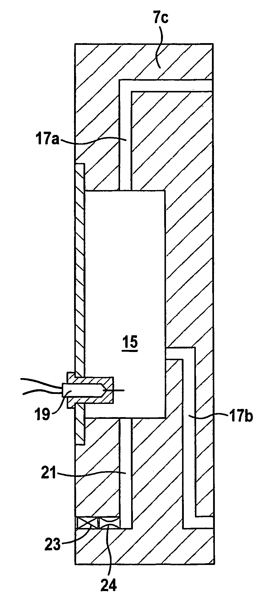
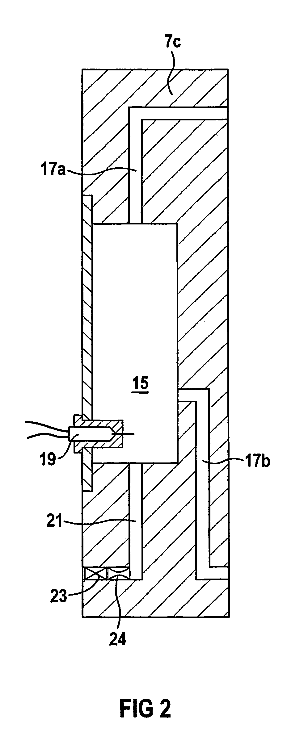
[0044]The end plates 7b and 7c delimit the humidifying cell stack 5a, and the end plates 7c, 7d and 7e delimit the fuel cell stacks 5b and 5c. The three end plates 7b, 7c and 7d are configured as intermediate plates with a number ...


PUM

PropertyMeasurementUnit
operating temperatureaaaaaaaaaa
operating voltageaaaaaaaaaa

Abstract

A fuel cell block includes a plurality of channels and pipings and a resulting plurality of connecting and sealed points. Vibrations of the fuel cell block, particularly in vehicles, lead to stress and fatigue of sealed points. This causes a safety problem during operation of the fuel cell block. In order to solve the problem, the fuel cell block includes an end plate, an operating material channel that goes through the end plate and an operating material control device arranged at least partly in the operating material channel. The operating material control device is integrated at least partly into the end plate.

Description

[0001]This application is the national phase under 35 U.S.C. § 371 of PCT International Application No. PCT / EP02 / 10373 which has an International filing date of Sep. 16, 2002, which designated the United States of America and which claims priority on European Patent Application number EP 01123174.3 filed Sep. 27, 2001, the entire contents of which are hereby incorporated herein by reference.FIELD OF THE INVENTION[0002]The invention generally relates to a fuel cell block having a number of planar fuel cells stacked on top of one another, an end plate and an operating-medium passage which runs through the end plate.BACKGROUND OF THE INVENTION[0003]During the electrolysis of water, the water molecules are broken down into hydrogen (H2) and oxygen (O2) by electric current. In a fuel cell, inter alia this operation takes place in reverse. Electrochemical combining of hydrogen and oxygen to form water results in the formation of electric current with a high level of efficiency and, if the...

Claims


Application Information

Patent Timeline
Patent Type & Authority Patents(United States)
IPC IPC(8): H01M2/02H01M4/88H01M8/0247H01M8/04119H01M8/241
CPCH01M8/0247H01M8/04156H01M8/241Y02E60/50H01M8/2483H01M8/04H01M8/0258H01M8/0267H01M8/242H01M8/2432
Inventor ISMAIER, NORBERTLERSCH, JOSEFMATTEJAT, ARNO
Owner SIEMENS AG
Why Eureka
Try Eureka