Compensated current differential relaying method and system for protecting transformer

a transformer and differential relaying technology, applied in emergency protective circuit arrangements, instruments, measurement devices, etc., can solve problems such as the limitation of methods, different currents, and need a substantial amount of tim

Inactive Publication Date: 2008-03-04
KIM YONG GYUN
View PDF8 Cites 9 Cited by
  • Summary
  • Abstract
  • Description
  • Claims
  • Application Information

AI Technical Summary

Benefits of technology

[0033]Accordingly, the present invention has been made to solve the above-mentioned problems occurring in the prior art, and an object of the present invention is to provide a current-differential relaying method and system for protecting a transformer more correctly by calculating and estimating an exciting current including a core-loss current and a magnetizing current, and, in particular, a current-differential relaying method and system which can protect the transformer correctly irrespective of the level of the remanent flux.

Problems solved by technology

However, when the transformer is energized, a large current flows through the primary winding and a large differential current occurs, which is referred to as a “magnetic inrush (or inrush)” and which results in a problem that the differential current occurs even when internal faults are not present.
However, these methods have the limit of application due to the difficulty of accurate discrimination between an internal fault and magnetic inrush, in that the magnitude of each harmonic component may be varied depending on whether or not there is the remanent flux in the iron core or depending on the magnitude of the remanent flux, and in that, when a power condition and a condition such as quality of transformer core material are changed, a large amount of the second harmonic component may be included even in the case of an internal fault.
Therefore, it needs a substantial amount of time until the harmonic components become zero and thus rapid fault detection is difficult.
And, the restraining or blocking methods using these harmonic components may prevent maloperation to some extent in the case of magnetic inrush or over-excitation, but they cannot prevent maloperation in the case that the differential current has a small amount of harmonic components.
However, there is a problem that, if there is the remanent flux, the errors occur because the locus of the magnetizing current versus flux deviates from the magnitization curve.
However, there is a problem that this method cannot apply to the over-excitation and the magnetic inrush on a loaded transformer, because the primary current and the differential current are not equal to each other.
However, according to this method, as the maximum remanent flux is 80% of the saturation-point flux, the bounded region becomes very wide and thus includes the region for an internal fault and the operating time for an internal fault is inevitably delayed.
These methods may perform a very rapid calculation without calculating the phasors of voltage and current.
However, they have the limit of application in that a large amount of data should be measured because they need the voltages as well as the currents of both terminals of the transformer.

Method used


Image

  • Compensated current differential relaying method and system for protecting transformer
  • Compensated current differential relaying method and system for protecting transformer
  • Compensated current differential relaying method and system for protecting transformer

Examples


case 1

[0084] Energization Angle of 0 deg, 0% Remanent Flux, No Load

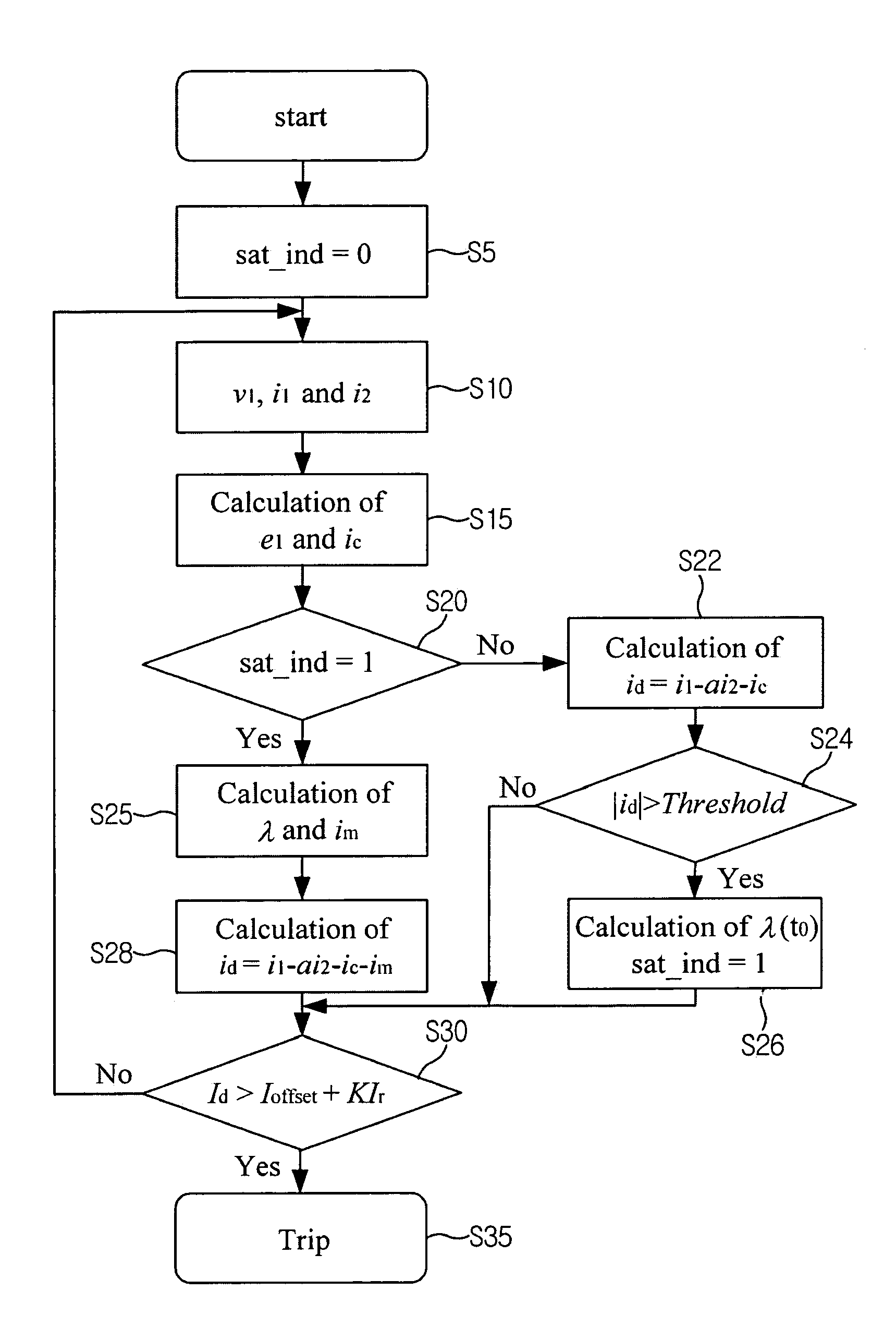
[0085]FIG. 8 shows the results for Case 1 according to the conventional differential current relay (left) and the present invention(right). The transformer is energized at 29.2 ms. In this case, the energization angle is zero and consequently the core was deeply saturated. The conventional differential current relay enters its operating region(see left in FIG. 8) and activates a trip signal at 5.2 ms after energization, but the present invention detects the start of saturation at 33.9 ms and calculates that the initial core flux was 345.4V. Equation (10) is used to calculate λ(t), and im(t) is obtained by inserting λ(t) into the magnetization curve. Therefore, when ic(t) and im(t) are subtracted from the measured differential current, the resulting compensated differential is reduced to a very small value and thus the relay does not enter the operating region and the trip signal remains inactive to correctly discriminate t...

case 2

[0086] Energization Angle of 0 deg, 80% Remanent Flux, No Load

[0087]FIG. 9 shows the results for Case 2 according to the conventional differential current relay (left) and the present invention (right). Since the energization angle is zero and the remanent flux is 80%, the primary current is forced to a value greater than the above Case 1. For the conventional relay, the relay is forced to enter its operating region and the trip signal is activated at 3.1 ms after energization (see left in FIG. 9). However, the compensated relay according to the present invention detects the start of saturation at 31.5 ms and calculates an initial core flux of 339.3 Vs. The compensated relay then calculates the magnetizing current and the core-loss current and uses them to derive the compensated differential current. Since the value of the compensated differential current remains small, the relay does not enter the operating region (see right in FIG. 9), and the trip signal remains inactive.

case 3

[0088] Energization Angle of 0 deg, 80% Remanent Flux, Full Load

[0089]FIG. 10 shows the results for Case 3 according to the conventional differential current relay (left) and the present invention (right). Since a full load is connected to the transformer secondary, the primary current is forced to a value greater than the above Case 2. Therefore, the differential currents used in the conventional relay and the present invention are similar to those in the above Case 2, whilst the restraining currents are different. The conventional relay issues a trip signal at 3.4 ms after energization, but the present invention detects the start of saturation at 31.8 ms and calculates an initial core flux of 343.8 Vs. Since the value of the compensated current remains very small, the relay does not enter the operating region (see right in FIG. 10), and the trip signal remains inactive.

[0090]These three cases clearly indicate that the compensated relay according to the present invention can discri...


PUM


Abstract

Disclosed is a compensated current differential relaying method and system for protecting a transformer more correctly by calculating and estimating an exciting current including a core-loss current and a magnetizing current, and, in particular, to a compensated current differential relaying method and system which can protect the transformer correctly irrespective of the level of remanent flux.

Description

BACKGROUND OF THE INVENTION[0001]1. Field of the Invention[0002]The present invention relates to a current-differential relaying method and system for protecting a transformer more correctly by calculating and estimating an exciting current including a core-loss current and a magnetizing current, and, in particular, to a current-differential relaying method and system which can protect the transformer correctly irrespective of the level of remanent flux.[0003]2. Description of the Prior Art[0004]As in the case of a generator or a power transmission line, differential relays have been widely used for protecting a transformer from internal faults. Herein the term ‘differential current relay’ indicates the method of calculating the difference of currents flowing through both terminals of the transformer (hereinafter, referred to as “differential current”), and detecting an internal fault when its value exceeds a certain predetermined value.[0005]FIG. 1 shows a configuration of a relay ...

Claims


Application Information

Patent Timeline
Patent Type & Authority Patents(United States)
IPC IPC(8): G01R31/00H02H7/045H02H3/28
CPCH02H7/045H02H7/0833G01R31/343
Inventor KANG, YONG-CHEOLKANG, SANG-HEE
Owner KIM YONG GYUN
Why Eureka
Try Eureka