Sensor including a sensor element having electrode terminals spaced apart from a connecting end thereof

a sensor element and sensor technology, applied in the direction of instruments, specific gravity measurement, material analysis, etc., can solve the problems of deterioration in connection reliability and undesirable deformation, and achieve the effects of reducing the insertion resistance, and preventing damage to the electrode terminal

Active Publication Date: 2008-03-11
NGK SPARK PLUG CO LTD
View PDF13 Cites 32 Cited by
  • Summary
  • Abstract
  • Description
  • Claims
  • Application Information

AI Technical Summary

Benefits of technology

[0020]In insertion of a conventional element whose rear end is chamfered, when metallic terminal members pass, through relative movement, over a chamfer after the element contacts the metallic terminal members, insertion resistance (push-in force) of the element is at a maximum. Since electrode terminals are provided next to the chamfer without any gap between the rear ends of the electrode terminals and the front end of the chamfer, when the metallic terminal members pass over the chamfer, the rear ends of the electrode terminals are subjected to such a strong force on the corresponding electrode terminals (layers) as to scrape or scratch off the electrode terminals in a frontward direction from their rear ends. Notably, herein, the rear end of an electrode terminal is an end of the electrode terminal located on a side toward the rear end of the element, and the front end of a chamfer is an end of the chamfer located on a side toward the front end of the element.
[0021]By contrast, even though the sensor element used in the present invention has a chamfer (bevel or round) formed on an edge defined by its rear end surface and the side surface having the electrode terminals formed thereon, the sensor element is formed as follows: the electrode terminals are formed such that rear ends of the electrode terminals are located away from the front end of the chamfer, keeping a gap between them; furthermore, a flat surface is present between the rear ends of the electrode terminals and the front end of the chamfer located on the side toward the front end of the element. Accordingly, during insertion of the element, a large force generated when the metallic terminal members pass over the chamfer is not directly applied to the rear ends of the electrode terminals. Specifically, such a large force by the metallic terminal members is relieved before the metallic terminal members reach the rear end edge of the electrode terminals. After the metallic terminal members slide on the flat surface, insertion resistance has already been greatly reduced. Accordingly, the force applied by the metallic terminal members to the corresponding electrode terminals is reduced to a level low enough to prevent damage to the electrode terminals. In other words, the metallic terminal members merely slide on the corresponding electrode terminals under a low insertion resistance, thereby preventing damage to the electrode terminals.
[0022]As described in (2) above, an appropriate length in the longitudinal direction of the above-mentioned flat surface is 0.5 mm or more. Insertion resistance (push-in force) of the element reaches its peak when the metallic terminal members pass over the chamfer towards the front end of the sensor element, and subsequently is greatly reduced. Thus, basically, the presence of the flat surface between the chamfer and the rear ends of the electrode terminals is sufficient, but to secure a sufficient effect of relieving insertion stress on the electrode terminals, the longitudinal length of the flat surface is preferably 0.5 mm or more, more preferably 1 mm or more. On the other hand, in further view of demand for reduction in size (length) of the element, a preferable upper limit of the longitudinal length of the flat surface can be set to 5 mm.
[0023]Preferably, as described in (3) above, the longitudinal length between the front and rear ends of the above-mentioned flat surface is longer than a longitudinal distance between the front end of the chamfer and the rear end surface of the sensor element. By employing such a length between the front and rear ends of the flat surface, insertion resistance can further be effectively reduced when sliding the metallic terminal members on the flat surface.
[0024]Preferably, as described in (4) above, the metallic terminal members further include projections (protrusions) projecting toward the corresponding electrode terminals and pressing against the electrode terminals. In the terminal connection structure in which the element is inserted, the thus-formed projections abut the corresponding electrode terminals locally or in a concentrated manner and thus in a kind of biting condition. Thus, the contact surface pressure is increased, thereby enhancing the stability or reliability of electrical connection. In the case where a conventional element is combined with the metallic terminal members each having projections formed thereon, when the projections pass over a chamfered portion, insertion resistance further increases due to such projections, thereby further increasing the risk of damage to the electrode terminals. By contrast, the present invention is free from such risk and can enhance the reliability of electrical connection owing to the presence of the flat surface provided between the electrode terminals and the chamfer.
[0025]Preferably, as described in (5) above, the metallic terminal members are configured such that, in a free state before complete engagement with the sensor element, the abutment portions are separated from the corresponding support portions and are configured such that, as the metallic terminal members are moved toward the front end of the sensor element from the rear end of the sensor element, the turnback portions are elastically deformed toward the corresponding support portions, and the abutment portions come to abut the corresponding support portions.

Problems solved by technology

However, intensifying the spring quality of the metallic terminal members 51 increases a force (push-in force) required for inserting the element 21 and involves the risk of undesirable deformation of the metallic terminal members 51 at the time of insertion of the element 21, with resultant deterioration in connection reliability.

Method used


Image

  • Sensor including a sensor element having electrode terminals spaced apart from a connecting end thereof
  • Sensor including a sensor element having electrode terminals spaced apart from a connecting end thereof
  • Sensor including a sensor element having electrode terminals spaced apart from a connecting end thereof

Examples


Embodiment Construction

[0060]The invention will next be described in detail with reference to the drawings. However, the present invention should not be construed as being limited thereto.

[0061]In the present mode, the invention is embodied as a full range air / fuel ratio sensor for detecting oxygen concentration in exhaust gas. Thus, the configuration of the sensor will first be described in detail.

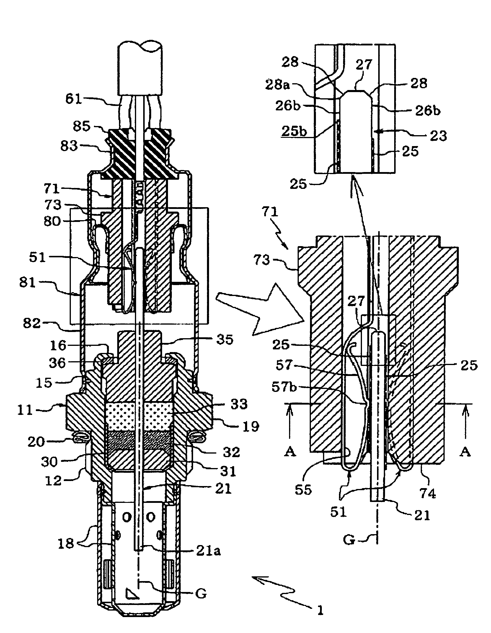
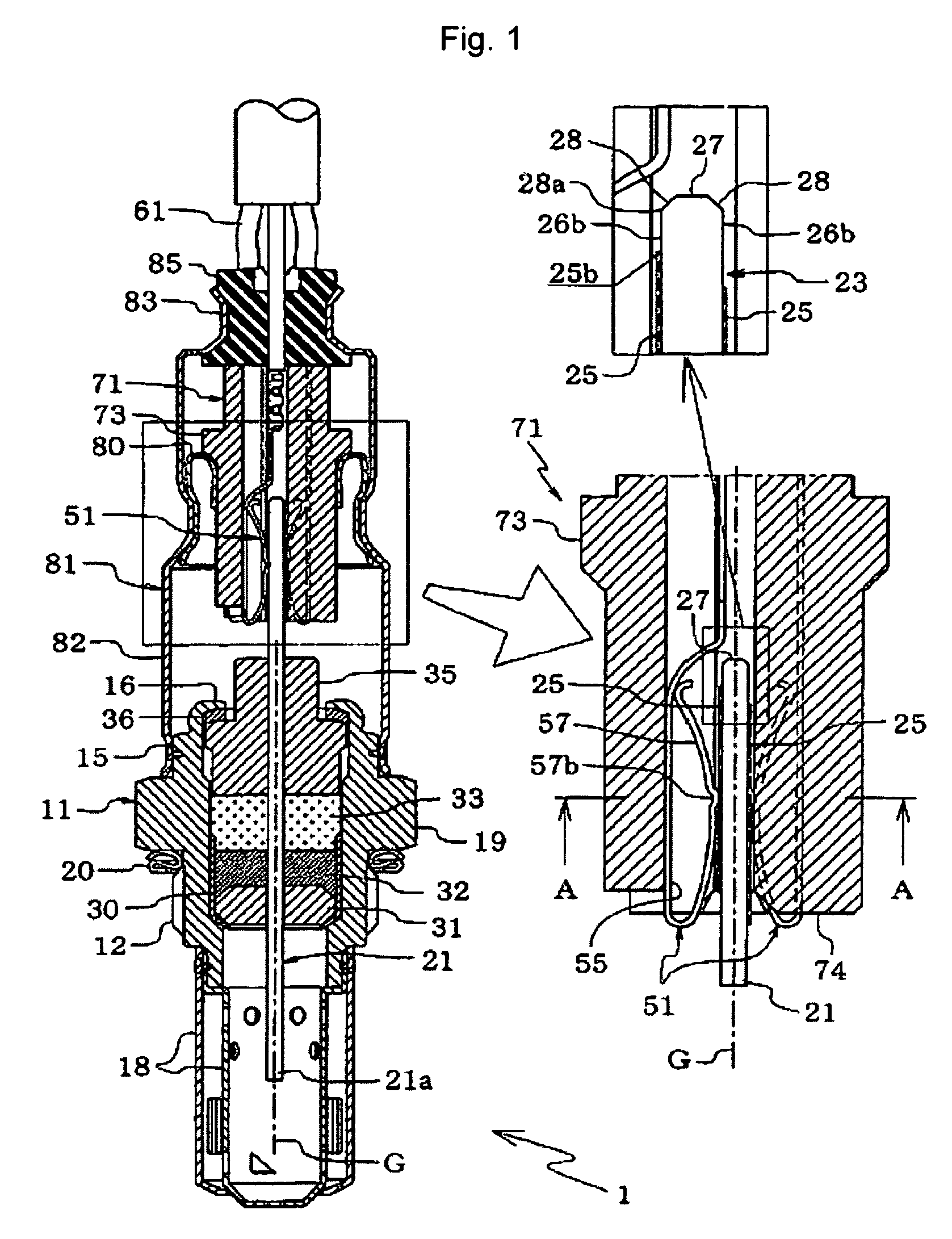
[0062]In the drawings, reference numeral 1 denotes a full range air / fuel ratio sensor. A sensor element 21 is airtightly fixed in the interior of a tubular metallic shell body 11 (hereinafter, also referred to as the shell body 11). The sensor element 21 is formed predominantly of ceramic, has an elongated plate-like shape having a rectangular cross section, and includes a detection portion (not shown) 21a located at its front-end portion (a lower portion in the drawings) to be directed toward a measurement object. The metallic shell body 11 is formed into a stepped cylindrical shape such that its inside diamet...


PUM

PropertyMeasurementUnit
distanceaaaaaaaaaa
lengthaaaaaaaaaa
longitudinal lengthaaaaaaaaaa

Abstract

A sensor having a terminal connection structure in which an elongated sensor element (21) is inserted, from its rear end through relative movement, into a metallic-terminal-member retainer. Metallic terminal members (51) are elastically deformed and pressed against corresponding electrode terminals (25) formed on side surfaces (26) of the sensor element. A chamfer (28) is formed on a rear edge of sensor element (21). Rear ends (25b) of the electrode terminals (25) are biased from the chamfer (28) toward a front end of the element (21). A flat surface (26b) is present between the rear ends (25b) of the electrode terminals (25) and a front end (28a) of the chamfer (28). During insertion of the element (21), a large force generated when the metallic terminal members (51) pass over the chamfer (28) is not directly applied to the rear ends (25b) of the electrode terminals (25), thereby preventing damage to the electrode terminals (25).

Description

BACKGROUND OF THE INVENTION[0001]1. Field of the Invention[0002]The present invention relates to a sensor having a sensor element for detecting a measurement object, such as a gas sensor for detecting the concentration of a certain component in exhaust gas or a like gas; for example, an oxygen sensor, a NOx sensor, or a HC sensor, or such as a temperature sensor for detecting the temperature of a gas.[0003]2. Description of the Related Art[0004]Conventional sensors employ various kinds of sensor elements (hereinafter, also referred to as elements), such as gas sensor elements, or temperature-sensitive elements, the sensor elements assuming a longitudinally elongated plate-like or rod-like shape. In such a sensor (for example, an oxygen sensor), a sensor element is fixed in the interior of a tubular metallic shell (metallic shell body) having a male-threaded portion to be mounted, for example, to the exhaust gas pipe of an engine. A front-end detection portion thereof projects from t...

Claims


Application Information

Patent Timeline
Patent Type & Authority Patents(United States)
IPC IPC(8): G01N7/00
CPCG01N27/4062G01N27/407G01N27/4077
Inventor MATSUO, KOUJIYAMADA, YUICHI
Owner NGK SPARK PLUG CO LTD
Why Eureka
Try Eureka