Cammed seal assembly with sealing ring having an angled leg portion and foot portion with elastomeric energizer element

a technology of cammed seals and sealing rings, which is applied in the direction of engine seals, mechanical devices, engine components, etc., can solve the problems of inability to withstand extreme high pressure and/or temperature, many prior art hydraulic seals are prone to leakage, and the complexity of construction adds undesirable weight and cos

Active Publication Date: 2008-03-11
GREENE TWEED TECH
View PDF72 Cites 48 Cited by
  • Summary
  • Abstract
  • Description
  • Claims
  • Application Information

AI Technical Summary

Problems solved by technology

One problem with the seals for high-pressure hydraulic applications generally known in the art is that the sealing or cap element is often not energized in a manner such that the sealing element applies uniform pressure to the cylindrical surface which it contacts.
Additionally, some of the hydraulic seals known in the art are not capable of withstanding the extreme high pressures and / or temperatures associated with highly-pressurized hydraulic systems.
Accordingly, many of the prior art hydraulic seals are prone to leakage due to excessive wear and / or non-uniform load distribution on the cap element.
It should be noted that it is desirable to use simple hardware particularly in aerospace applications, since complexity of construction adds undesirable weight and cost.

Method used


Image

  • Cammed seal assembly with sealing ring having an angled leg portion and foot portion with elastomeric energizer element
  • Cammed seal assembly with sealing ring having an angled leg portion and foot portion with elastomeric energizer element
  • Cammed seal assembly with sealing ring having an angled leg portion and foot portion with elastomeric energizer element

Examples


Embodiment Construction

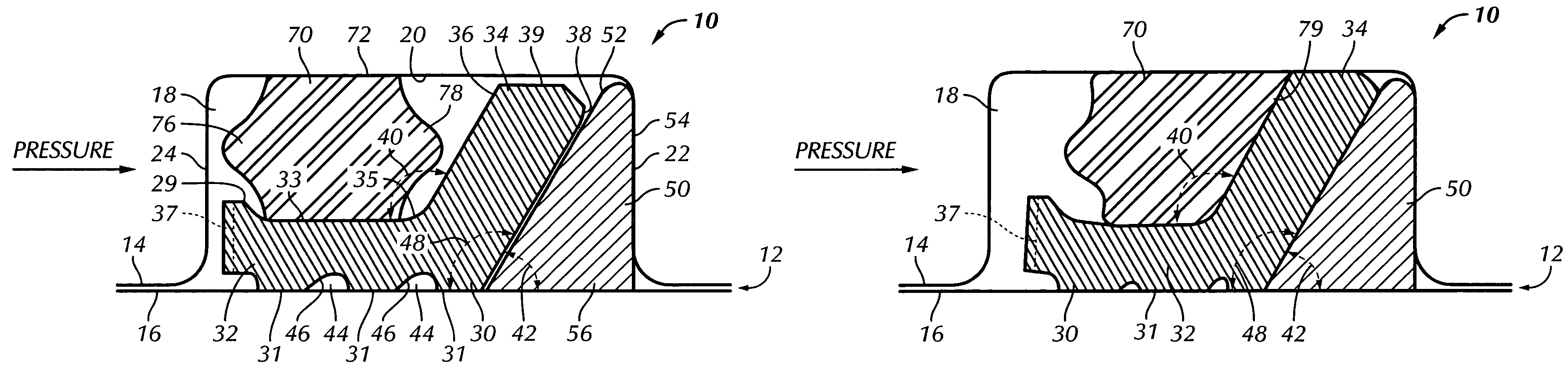
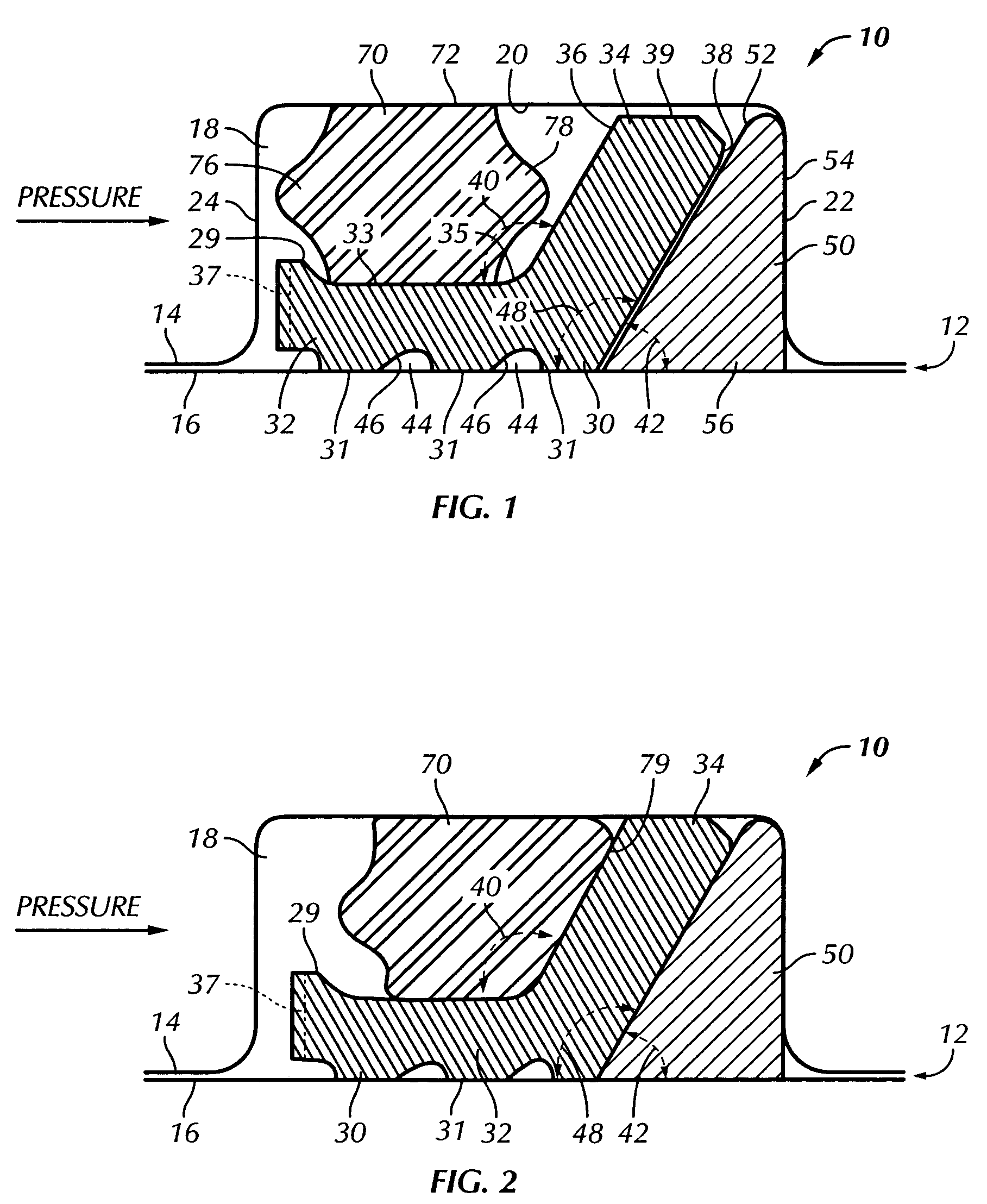
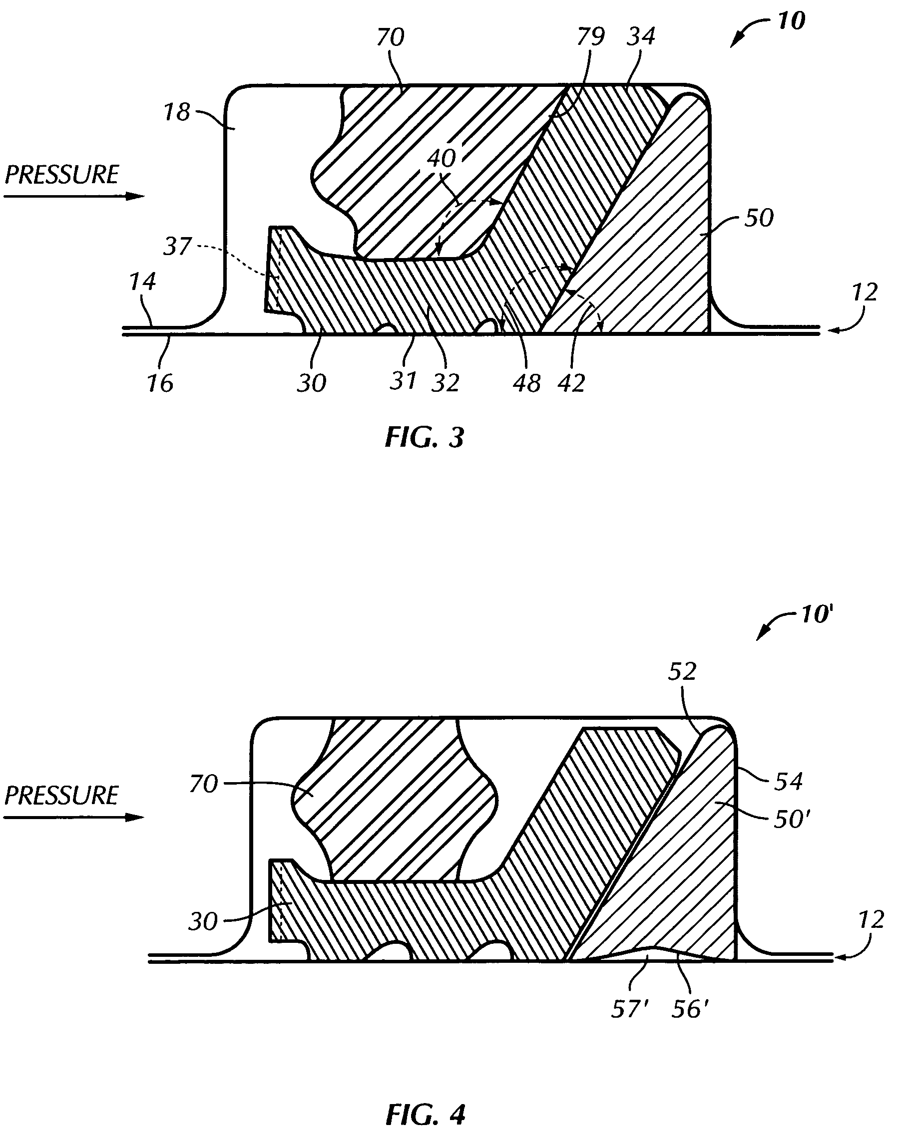
[0016]Certain terminology is used in the following description for convenience only and is not considered limiting. The words “right,”“left,”“lower,” and “upper” designate directions in the drawings to which reference is made. The words “inwardly” and “outwardly” refer to directions toward and away from, respectively, the geometric center of the seal assembly and designated parts thereof. The terminology includes the words above specifically mentioned, derivatives thereof and words of similar import.

[0017]Referring now to the drawings in detail, wherein like numerals are used to indicate like elements throughout, there is shown in FIGS. 1-3 a seal assembly, generally designated 10, in accordance with a preferred embodiment of the present invention. The seal assembly 10 is used for sealing a clearance space or gap 12 between first and second mating operational surfaces 14, 16, respectively. The first surface 14 includes a generally annular seal assembly receiving groove 18 therein. T...


PUM


Abstract

A seal assembly seals first and second operational surfaces spaced apart by a gap. The first surface includes a seal groove having a base surface and first and second side surfaces. A sealing element in the seal groove has a foot portion extending parallel to the base surface which engages the second operational surface. A leg portion extending from the foot portion toward the base surface has first and second surfaces. A back-up ring adjacent to the sealing element prevents extrusion of the sealing element into the gap. A first side of the back-up ring mates with the second surface of the leg portion, and a second side mates with one of the first and second side surfaces of the seal groove. An energizer element located between the base surface and the foot portion applies uniform pressure to the leg and foot portions when the energizer element is compressed.

Description

BACKGROUND OF THE INVENTION[0001]The present invention relates to a seal assembly for sealing a clearance space or gap between first and second displaceable cylindrical surfaces, and more particularly to a seal assembly which includes an inclined “L” or foot-shaped element in contact with one of the cylindrical surfaces.[0002]Seal assemblies designed for leakage control of fluid in pressurized hydraulic systems are generally known in the art. Such seals may be found, for example, in aerospace applications, including flight-controls, landing gears and hydraulic actuators. The seals used in such applications may have a variety of different geometries, while all performing generally the same function. Seals of different shapes and / or materials are better suited for different types (e.g., operating conditions) of applications. One problem with the seals for high-pressure hydraulic applications generally known in the art is that the sealing or cap element is often not energized in a mann...

Claims


Application Information

Patent Timeline
Patent Type & Authority Patents(United States)
IPC IPC(8): F16J15/00
CPCF16J15/166F16J15/3208F16J15/3236
Inventor HOLT, AUGUSTUS BROOKSROBERTS, PAUL E.SCHOFIELD, ALAN P.
Owner GREENE TWEED TECH
Why Eureka
Try Eureka