Lift-assisted manhole cover

a manhole cover and lift technology, applied in the field of manhole covers, can solve the problems of partially blocked access to the manhole, the manhole cover may not have the space to swing a full vertical arc, and the cost of providing the necessary spring force to assist the cover in such a manner is prohibitive, and achieves the effect of simple and effective lift-assisted and easy raising

Inactive Publication Date: 2008-03-11
EAST JORDAN IRON WORKS
View PDF21 Cites 24 Cited by
  • Summary
  • Abstract
  • Description
  • Claims
  • Application Information

AI Technical Summary

Benefits of technology

[0006]In one embodiment, movement of the cover and shaft is achieved by operation (e.g. rotation) of the threaded shaft. In this embodiment, the shaft may be threadedly interconnected with the frame such that rotation of the shaft causes to move linearly with respect to the frame. In one embodiment, the threaded shaft is a bolt that is fitted freely through the mounted tab and threadedly engaged with the frame. The bolt may be firmly interlocked with the cover by a cotter pin or other similar mechanism to, among other things, resist tilting of the cover about the bolt and to translate linear movement of the bolt into linear movement of the cover.
[0007]The present invention is a simple and effective lift-assisted manhole cover. In those embodiments with an externally-located lift-assist mechanism, access to the manhole is not obstructed by the lifting mechanism when the cover is fully opened because the mounting tab is positioned outside of the manhole. In some embodiments, the lift-assist mechanism is located below the cover, thereby permitting the manhole assembly to have a flat, uniform upper surface. In those embodiments that include a threaded interconnection between the shaft and the frame, the cover is easily raised and lower by operation of the shaft. Some embodiments include an interlocking relationship between the cover and the shaft that helps to maintain the cover substantially perpendicular with respect to the shaft.

Problems solved by technology

Unfortunately, in some circumstances, the cost of providing the necessary spring force to assist the cover in such a manner is prohibitive.
Further, the manhole cover may not have room to swing a full vertical arc.
Unfortunately, in Galvanetto, access to the manhole is partially blocked even when the cover is fully opened.
Wade suffers in that the spring and locking mechanism extend substantially higher than the surface of the manhole cover making it difficult to drive a car or walk over the manhole cover.

Method used


Image

  • Lift-assisted manhole cover
  • Lift-assisted manhole cover
  • Lift-assisted manhole cover

Examples


Embodiment Construction

I. General Description

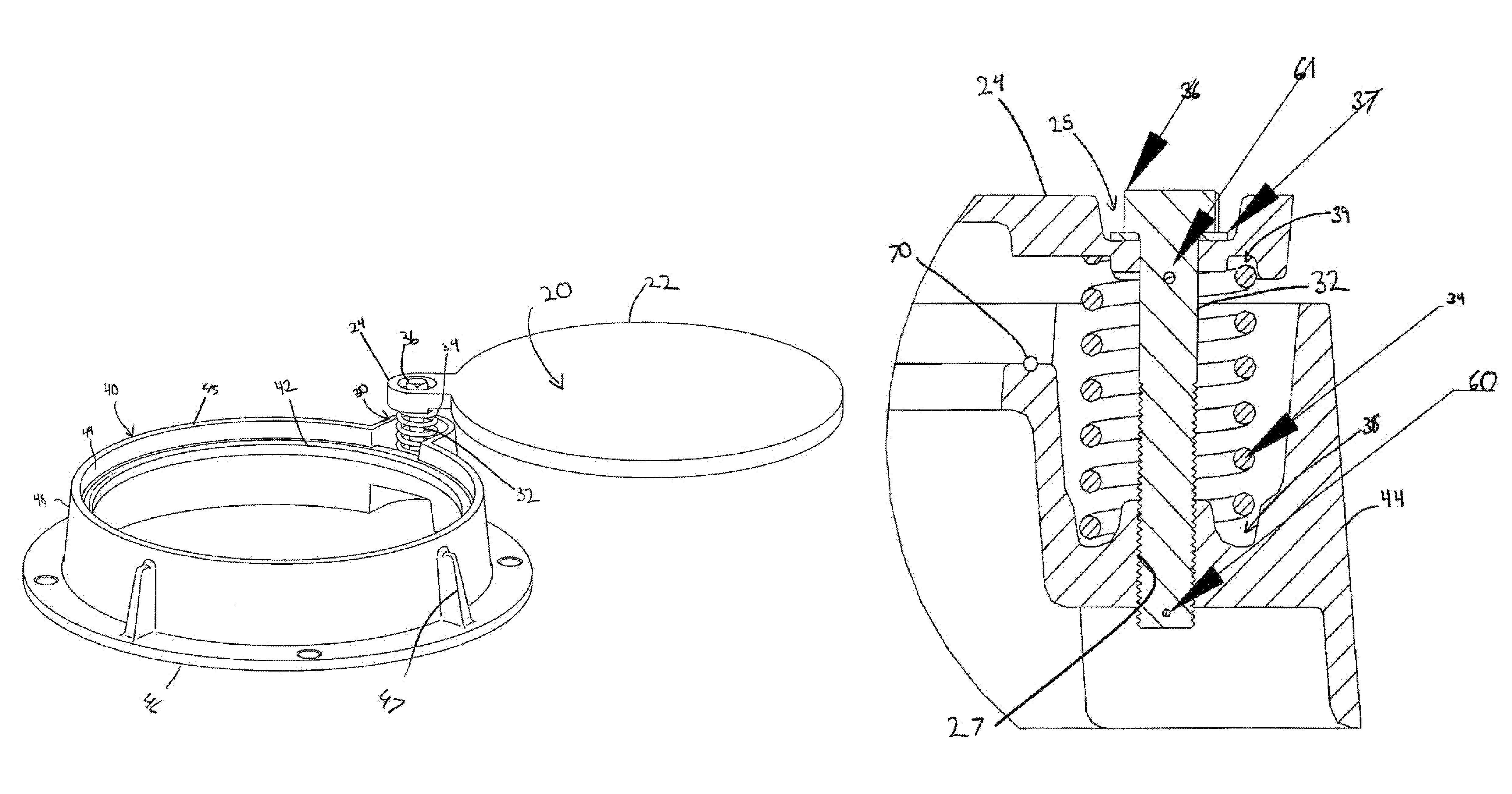
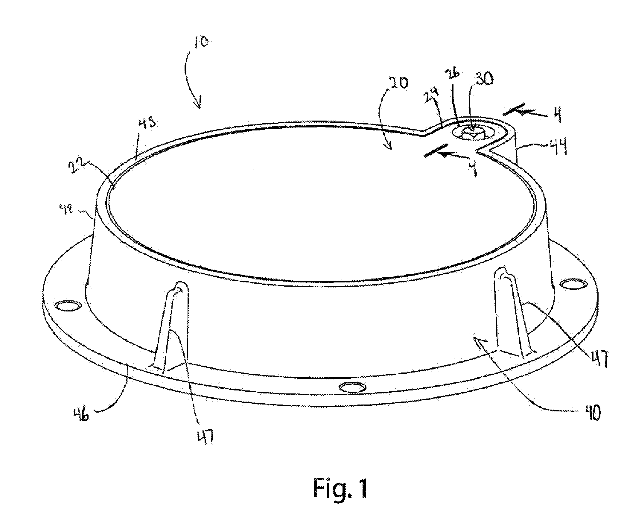
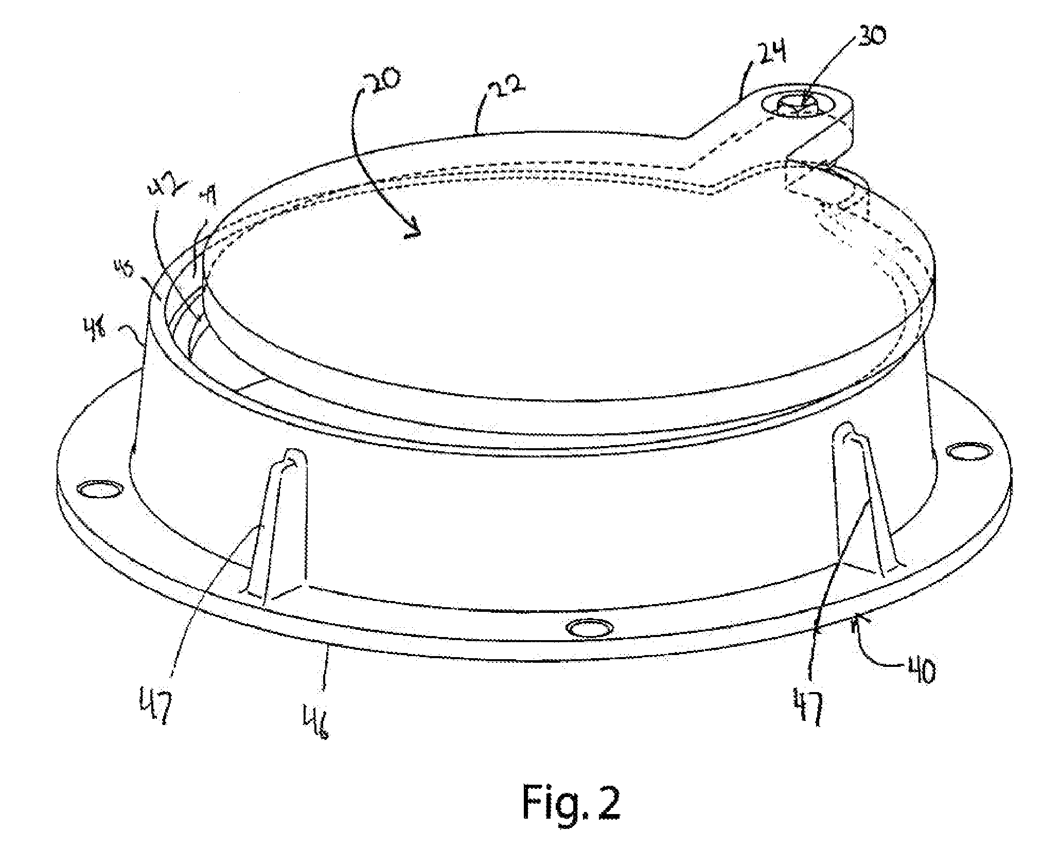
[0013]An embodiment of the lift-assisted manhole cover assembly of the present invention is illustrated in FIGS. 1-5, and generally designated 10. The manhole cover assembly 10 generally includes a manhole cover 20, a frame 40, and a lifting element such as a threaded shaft 32 or a spring 34 for assisting in lifting the manhole cover 20 off of the frame 40. In one embodiment, a portion of the manhole cover 20 extends beyond the general periphery of the cover to form a mounting tab 24. The shaft 32 interacts with the mounting tab 24 to provide a pivot point external to the general periphery of the cover.

[0014]The manhole cover assembly 10 may be installed with bedding or infills to provide a flush surface capable of being driven or walked on without obstructions extending above the surface. In operation, the lifting element provides vertical assist to help the cover 20 clear the frame 40. The cover 20 may be swung horizontally to an open position where the cover...


PUM


Abstract

A lift-assisted manhole cover assembly with a flush surface and external pivot shaft. The cover includes a mounting tab that extends beyond the general periphery of the cover. The mounting tab may be connected to a shaft that is threadedly engaged with the frame. A spring may be mounted between the frame and the mounting tab, for example, in a sleeve, to provide a mechanical assist in lifting the cover. The sleeve may be disposed outside the manhole opening where it does not block access to the manhole opening.

Description

BACKGROUND OF THE INVENTION[0001]The present invention relates to manhole covers, and more particularly to lift-assisted manhole covers.[0002]Manhole covers are well known. Generally, a manhole cover is a removable plate forming the lid over the opening of a manhole to, among other things, prevent someone from falling in and to keep unauthorized persons out. Manhole covers often weigh more than 100 pounds, partly because the weight keeps them in place when traffic passes over them, and partly because they are often made out of cast iron, sometimes with infills of concrete. This makes them inexpensive and strong, but heavy. They often feature pick holes, in which a hook handle is inserted to lift them up.[0003]Because of the weight of manhole covers, various efforts have been made to make them easier to open. More specifically, spring-assisted manhole covers are disclosed in U.S. Pat. Nos. 6,446,307 to Wilkins, 5,788,406 to Hernandez, 5,507,590 to Argandona, and U.S. Patent Applicati...

Claims


Application Information

Patent Timeline
Patent Type & Authority Patents(United States)
IPC IPC(8): B65D43/18
CPCE02D29/1418Y10T137/7021
Inventor JOHNSON, JEREMY I.VELDBOOM, LEE M.BEAL, SCOTT B.BARNUM, HERBERT CARLAUSTIN, WILLIAM R.MALPASS, JAMES F.LOVISKA, TODD C.RACHWITZ, BRIAN J.GARRINGER, REX A.SNYDER, JOHN H.
Owner EAST JORDAN IRON WORKS
Why Eureka
Try Eureka