Rotary electrical machine and electric vehicle having the same

a technology electric vehicles, which is applied in the direction of magnetic circuit rotating parts, magnetic circuit shape/form/construction, cycles, etc., can solve the problems of inevitably large external size complicated structure of rotary electrical machines, and inability to meet the needs of electric vehicles, etc., to achieve the effect of strengthening the magnetic field

Inactive Publication Date: 2008-03-11
YAMAHA MOTOR CO LTD
View PDF50 Cites 25 Cited by
  • Summary
  • Abstract
  • Description
  • Claims
  • Application Information

AI Technical Summary

Benefits of technology

[0015]In view of the circumstances, an aspect of the present invention is to decrease external dimensions of a rotary electrical machine, and also to simplify the structure of the machine, in which a rotor is moved in an axial direction to urge the rotor toward or away from a stator. The movement of the rotor toward or away from the stator strengthens or weakens, respectively, the magnetic field between the rotor and the stator. Therefore, the strength of the magnetic field between the rotor and the stator is controllable.
[0016]Also, another aspect of the present invention is to make the rotor of the rotary electrical machine movable in the axial direction without increasing external dimensions of the machine or making the structure of the machine more complicated.
[0024]In another mode, when the rotary electrical machine operates as the electric motor, if the torque transmitted from the rotor to the rotational shaft decreases, then the rotor moves away from the stator, and the magnetic field between the rotor and the stator weakens. Thus, when the load applied to the rotational shaft is small, the rotational shaft can rotate at a high speed. Thereby, for example, if such a rotary electrical machine is applied to the electric vehicle, the running speed of the vehicle when the output torque is small (e.g., under a low torque condition) can be high.
[0027]Further, in one mode, when the rotor has moved to a desired position, if the force by which the rotor position changing mechanism forces the rotor to recede from the stator and the attractive magnetic force generated between the rotor and the stator balance with each other, the rotor can be placed at a desired position regardless of the rotational speed of the rotational shaft. That is, the voltage generated by the rotary electrical machine can be nearly fixed. Thus, by adjusting the force that makes the rotor recede from the stator, the generating characteristic of the rotary electrical machine (or the braking characteristic thereof when the rotary electric machine is used for regenerative braking) can be freely set. If the generated voltage is charged into a secondary battery, generating circuits such as, for example, a voltage rising circuit or a voltage lowering circuit can be simplified. Also, the characteristic of the rotary electrical machine can be adjusted so as to be suitable for charging.
[0029]As thus described, according to the present rotary electrical machine, the compact and simple structure can make the rotor approach or recede from the stator. Thus, the strength of the magnetic field between the rotor and the stator can be controlled. In addition, the rotor can be moved in the axial direction of the rotational shaft without requiring an increase in the external dimensions of the machine or complicating the structure of the machine.

Problems solved by technology

Accordingly, a problem arises in that the external size of the rotary electrical machine is inevitably large.
Also, because the receiving apertures, the auxiliary yokes and the like described above are necessary in addition to the centrifugal governor, another problem arises in that the structure of the rotary electrical machine is complicated.
Thus, the size of the rotary electrical machine is inevitably large.
A large space thus is needed for mounting the rotary electrical machine.

Method used


Image

  • Rotary electrical machine and electric vehicle having the same
  • Rotary electrical machine and electric vehicle having the same
  • Rotary electrical machine and electric vehicle having the same

Examples


first embodiment

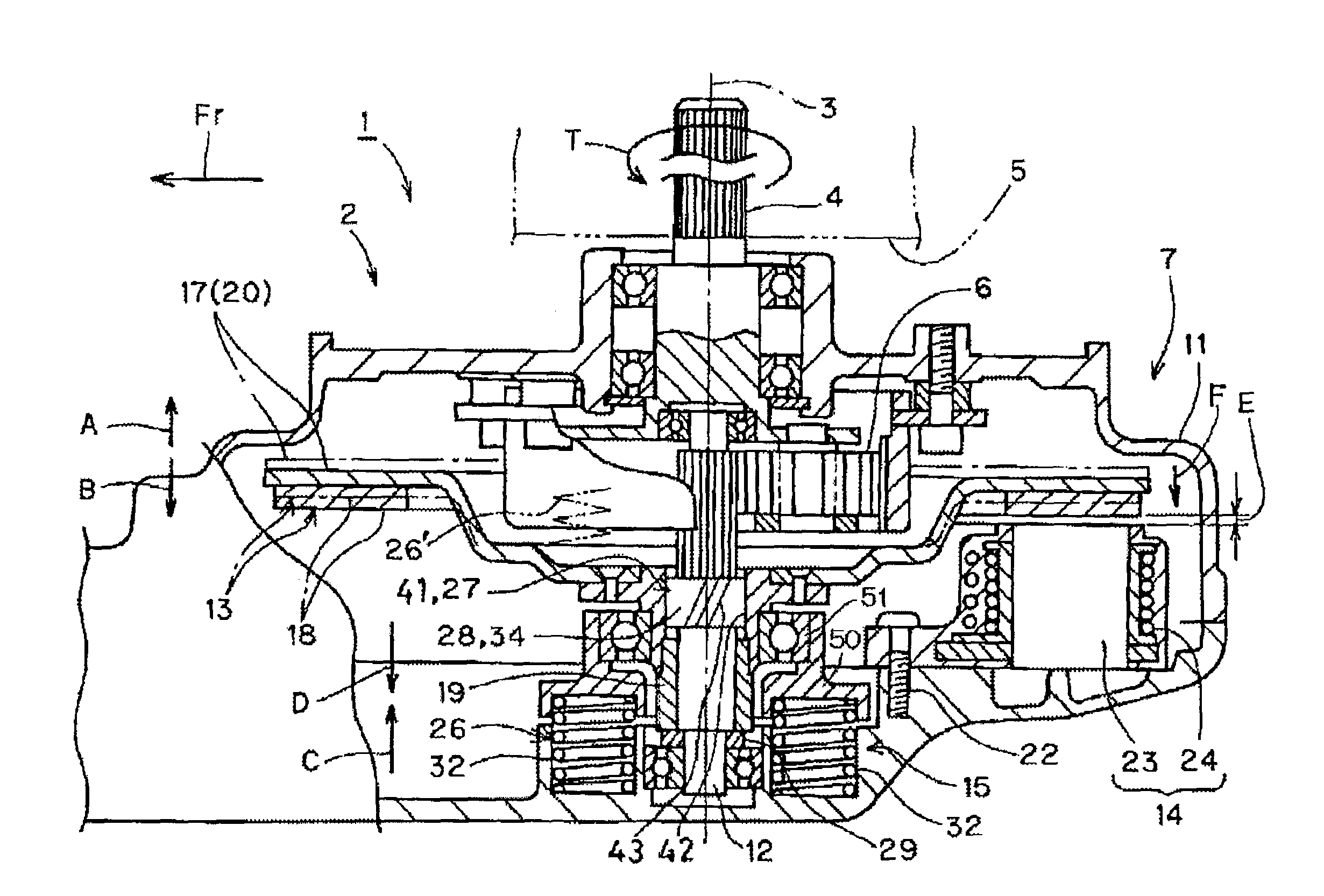
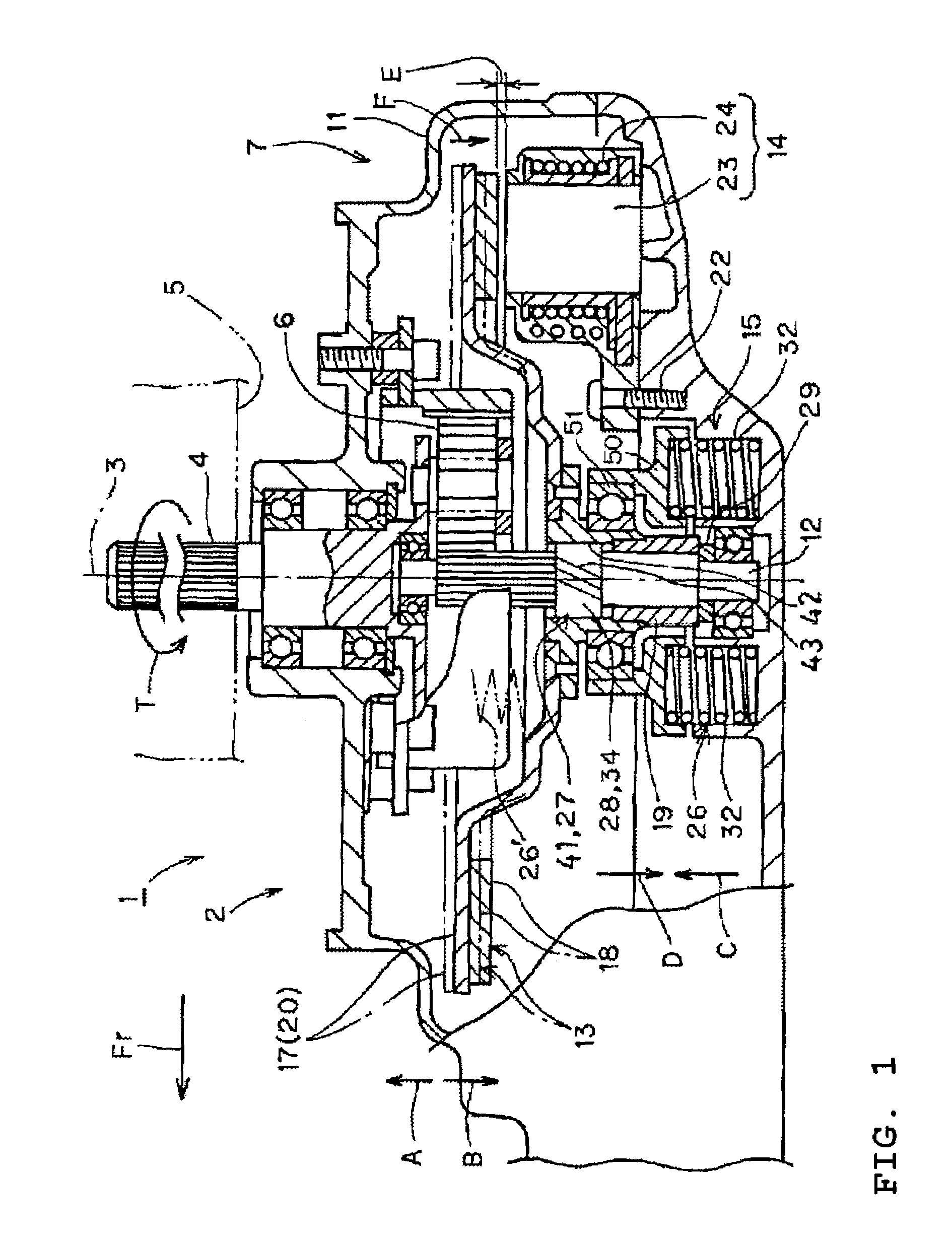
[0039]With reference to FIGS. 1 and 2, a first embodiment will be described. In FIG. 1, the reference numeral 1 indicates the electric vehicle. The electric vehicle 1 of this embodiment is a motorcycle which is a kind of straddle type vehicle. However, the electric vehicle according to the present invention is not limited to the straddle type vehicle. The arrow Fr indicates the forward direction of the electric vehicle 1 (e.g., toward the front end of the vehicle 1).

[0040]The electric vehicle 1 includes a vehicle body, which is not shown, and a rear arm 2 supported by the vehicle body for up and down swing movement of the arm 2 relative to the vehicle body. The rear arm 2 has an axle 4 at a swing end in a rear portion of the rear arm 2, the axle 4 extending in a width direction of the vehicle body (e.g., up to down direction of FIG. 1) and being supported for rotation about an axis 3. A drive wheel 5 which in the illustrated embodiment, is a rear wheel, is coupled with the axle 4. T...

fourth embodiment

[0105]According to the moving member 41 thus constructed, via a simple movement in which the rotational shaft 12 and the rotor 13 simply helically rotate relative to each other, the gap size E between the rotor 13 and the stator 14 can be changed, or the size of the areas of the rotor 13 and the stator 14 that face each other can be changed (see the fourth embodiment). The characteristic of the rotary electrical machine 7 can thus be changed using the moving member 41 via the simple structure.

[0106]The moving member 41 is formed with an engaging structure in which the rotational shaft 12 and the rotor 13 engage with each other, and engaging portions thereof helically extend about the axis 3 of the rotational shaft 12. When the force component of the transmission torque T is generated between the rotational shaft 12 and the rotor 13, the force component is given to either one of the rotational shaft 12 and the rotor 13 from the other one through the engaging portions. Because the eng...


PUM


Abstract

A rotary electrical machine includes a rotational shaft supported by a housing for rotation about an axis, a rotor coupled with the rotational shaft, and a stator fixed to the housing and oriented to face the rotor. A rotor position changing mechanism moves the rotor in an axial direction of the rotational shaft using a portion of a torque transmitted between the rotational shaft and the rotor as a driving force. The rotor position changing mechanism controls the strength of the magnetic field between the rotor and the stator by moving the rotor toward or away from the stator.

Description

CROSS-REFERENCE TO RELATED APPLICATIONS[0001]This application is a continuation of PCT Application No. PCT / JP2004 / 007603, which was filed on Jun. 02, 2004 and published in Japanese on Jan. 27, 2005 as WO 05 / 008865 A1, the entire contents of which are incorporated herein by reference and should be considered a part of this specification. The above PCT application claims priority to Japanese Patent Application No. 2003-199078, filed on Jul. 18, 2003.BACKGROUND OF THE INVENTION[0002]1. Field of the Invention[0003]The present invention relates to a rotary electrical machine and an electric vehicle having the same.[0004]2. Description of the Related Art[0005]Conventional, rotary electrical machines have a rotor, a rotational shaft attached to the rotor, and a stator. The strength of the magnetic field between the rotor and the stator is controlled in response to a rotational speed of the rotor. In this kind of rotary electrical machine, the characteristic of the rotary electrical machine...

Claims


Application Information

Patent Timeline
Patent Type & Authority Patents(United States)
IPC IPC(8): H02K1/06H02K7/116H02K21/00H02K21/16H02K21/24
CPCH02K7/116H02K21/026B62K2204/00H02K21/24Y02T10/641H02K21/16Y02T10/64
Inventor NAITOU, SHINYAHINO, HARUYOSHIMUROTA, KEIKOISHIHARA, HIROYUKITERADA, JUNJIONO, TOMOHIRO
Owner YAMAHA MOTOR CO LTD
Why Eureka
Try Eureka