Differential amplifier, and data driver of display device using the same

a technology of data drivers and amplifiers, applied in the direction of differential amplifiers, amplifiers with semiconductor devices/discharge tubes, dc-amplifiers with dc-coupled stages, etc., can solve the problem of inability to perform high-accuracy output of internally divided voltages, and achieve high-accuracy output, reduce the number of input voltages, and reduce the effect of transistors

Active Publication Date: 2008-03-11
HANNSTAR DISPLAY CORPORATION
View PDF9 Cites 18 Cited by
  • Summary
  • Abstract
  • Description
  • Claims
  • Application Information

AI Technical Summary

Benefits of technology

[0032]Further, as the voltage difference between the Vin1 and the Vin2 is increased, the absolute value of the error is increased.
[0068]Still further, lower cost of the display device including the data driver can also be implemented. Narrower frame of the display device can also be achieved.

Problems solved by technology

This means that, high-accuracy output of internally divided voltages cannot be performed using gray scales corresponding to voltage ranges in which the errors are produced, and this is a critical problem in the data driver that is required to perform high-accuracy voltage output.

Method used


Image

  • Differential amplifier, and data driver of display device using the same
  • Differential amplifier, and data driver of display device using the same
  • Differential amplifier, and data driver of display device using the same

Examples


first embodiment

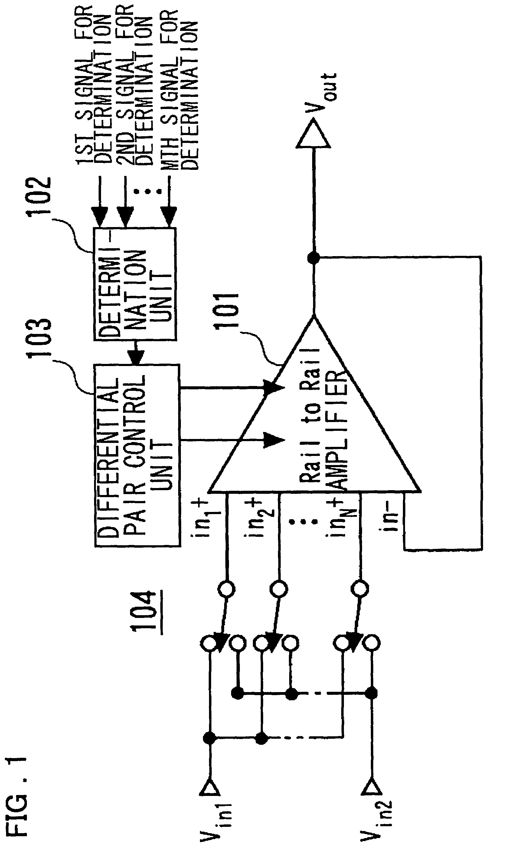
[0096]FIG. 1 is a diagram showing a configuration of a first embodiment of the present invention. Referring to FIG. 1, a differential amplifier according to this embodiment mode includes a Rail-to-Rail amplifier 101 having a plurality of differential pairs of same polarities, a determination unit 102, and a differential pair control unit 103. The determination unit 102 determines whether to stop the differential pairs or not according to M signals for determination (in which M is a predetermined positive integer) including an output voltage. The differential pair control unit 103 controls to operate or stop the differential pairs. By the way, the Rail-to-Rail amplifier 101 in this embodiment can be applied to the Rail-to-Rail amplifier having an arbitrary configuration including a plurality of differential pairs of the same polarities, such as an amplifier 3300 shown in FIG. 24. Incidentally, a switch 104 has the same function as a switch 3150 described with reference to FIG. 22. Ei...

second embodiment

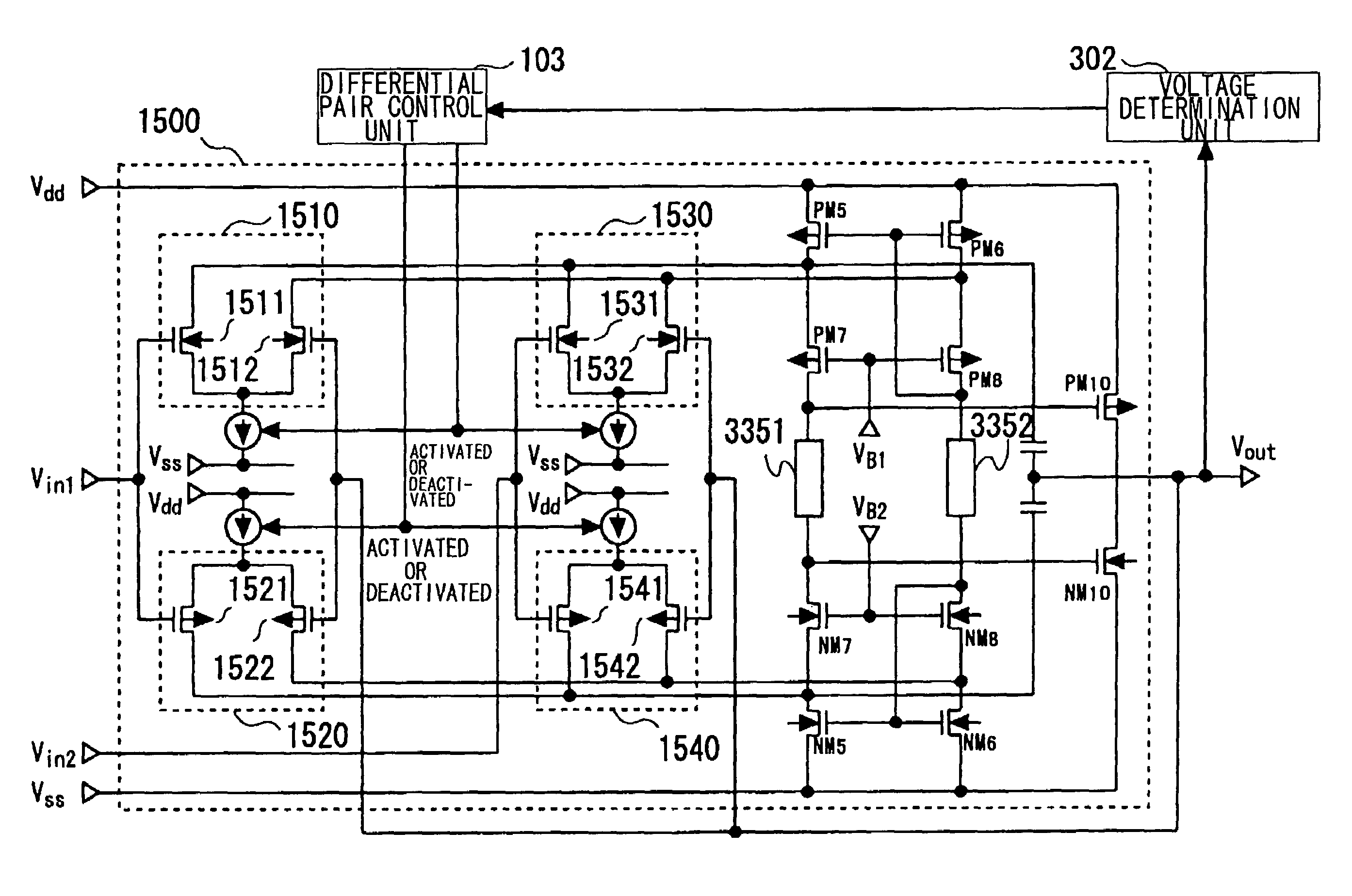
[0115]FIG. 3 is a diagram showing a configuration of a second embodiment of the present invention. The second embodiment of the present invention will be described, using FIG. 3. The second embodiment of the present invention is obtained by replacing the determination unit in the first embodiment by a voltage determination unit 302.

[0116]An operation of the present embodiment will be described. In the following description, the output voltage will be set to Vout, an error-producing voltage on a low-potential supply voltage side, at which an error on the low-potential supply voltage side is produced, will be set to be in a range from a Vss to a VSN, and an error-producing voltage on a high-potential supply voltage side, at which an error on the high-potential supply voltage side is produced, will be set to be in a range from the VSP to a Vdd.

[0117]First, a voltage that changes in the form of a monotonous increase or a monotonous decrease according to the output voltage Vout is suppli...

third embodiment

[0146]Next, a third embodiment of the present invention will be described, using FIG. 6. Referring to FIG. 6, the third embodiment is obtained by replacing the determination unit in the first embodiment by a polarity determination unit 602.

[0147]In order to describe the present embodiment, a polarity signal in a liquid crystal display device will be briefly described, first. In the liquid crystal display device, a driving method in which the polarity of a voltage applied to each liquid crystal element is reversed every certain period is generally employed.

[0148]Then, as shown in FIG. 7, a period in which a positive voltage is applied to a common voltage Vcom (the voltage of an opposed electrode of a TFT substrate) is referred to as a “positive polarity period”, while a period in which a negative voltage is applied to the common voltage Vcom is referred to as a “negative polarity period”.

[0149]To the data driver of the liquid display device, the signal (polarity signal) synchronized ...


PUM


Abstract

Disclosed is a Rail-to-Rail amplifier including a plurality of differential pairs of a first conductivity type and a plurality of differential amplifiers of a second conductivity type each with one of an input pair thereof constituting an input terminal, a differential amplifier that outputs an output voltage according to the range of provided supply voltage, a determination unit for determining whether to stop operations of the differential pairs of the first conductivity type or the second conductivity type according to a predetermined input signal, and a differential pair control unit for stopping the operations of the differential pairs of the first conductivity type or the second conductivity type according to the output signal of the determination unit.

Description

FIELD OF THE INVENTION[0001]The present invention relates to a differential amplifier. More specifically, the invention relates to the differential amplifier suitable for being applied to the data driver of a liquid crystal display device or the like and a display device that uses it.BACKGROUND OF THE INVENTION[0002]In recent years, liquid crystal display devices (LCDs) featuring thinness, lightweight, and low power consumption have become widespread, and have often been used as display units of mobile devices such as cellular phones (mobile phones), PDAs (personal digital assistants), and notebook PCs. Recently, however, a technology for supporting a larger screen and moving images of the liquid crystal display device has developed, so that implementation of large-screen display devices and large-screen liquid crystal television sets of a stationary type as well as those for mobile applications has become possible. As these liquid crystal display devices, the liquid crystal display...

Claims


Application Information

Patent Timeline
Patent Type & Authority Patents(United States)
IPC IPC(8): H03F3/45
CPCH03F3/45179H03F3/72
Inventor ISHII, JUN-ICHIROUTSUCHI, HIROSHI
Owner HANNSTAR DISPLAY CORPORATION
Why Eureka
Try Eureka